You can actually build this temperature-controlled CCS based on, say, IRF610/9610 - it will require resistor values update and preferably higher rails (at least the positive one), as the MOSFET-based CCS requires even more headroom, than the BJT-based one.
I would leave the BJTs though 😉
I would leave the BJTs though 😉
You can actually build this temperature-controlled CCS based on, say, IRF610/9610 - it will require resistor values update and preferably higher rails (at least the positive one), as the MOSFET-based CCS requires even more headroom, than the BJT-based one.
I would leave the BJTs though 😉
As long as the bjt do not is in signal path it is for me still a allfet circlotron, even my idea was to replace the ccs on ltp input diff for bjt because of very much drift Jfet, that can be corrected if i can find the zero drift point of jfet, who can als get positieve, even can it be used for a correcting function for idle current.
A mosfet current mirror is maybe also a option, I to test this stuff.
The removal of the ccs in the lower part of the VAS diff is removed because it did make idle current unstable and is there for nothing, the ciclotron need a low impedance pathto there gates because of the capacitance who is big for irf240.
thanks for idea.s
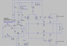
Kees, this is the way I would do it.
I like to use TO-126 devices in thermal feedback as they are easy to place on a heatsink.
Make around 1-2mA through Q2 and as much as you need through Q1.
The higher the temperature of Q2 -> the lower the current through Q1 = the lower the bias.
Cheers,
Valery
P.S. Correct the resistors' values according to the currents you require.
I have tryed this, but it still runs out, there is a treshold in the irfp250n mosfet where it runs to high in idle and a setup where it drops, idling on 120 mA or such.
The CCS used on the lower part of the LTP is extremely sensitive when I do warm it with my vingers the idle current runs up with 1.2 amps very quick, this Jfet is quite sensible, I have heart of a Jfet setup where it do not change with temperature, so called TC=0.
Attachments
Last edited:
Hi X and al the followers.
The ccs for using as a idle compensation did not work
properly, the runout is to much for it, as it is a circlotron the temp runout is twice as fast because two half amp are present.
The only way to get it right is a NTC resistor on the power mosfet, these resistors are fast enough to track them.
I can even change the temp sensor transistor for a ntc and tune it, then it will give enough for me, or this autobias system.
For the CCS jfet, I have now a opposite run of idle with temperature, by lowering input voltage to 8.2 volts. and is much better now.
regards
Attachments
The ccs for using as a idle compensation did not work . . . The only way to get it right is a NTC resistor on the power mosfet, these resistors are fast enough to track them.
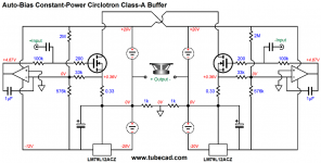
If you are still open to other ideas, I'd like to offer this one as my earlier circuit did not explicitly address thermal drift and OS temp compensation issues. I have not built it, but have enough experience with similar circuits to believe what my sim is telling me. If interested, I suggest you sim this for yourself and see how it behaves vs. your current solution.
Attachments
If you are still open to other ideas, I'd like to offer this one as my earlier circuit did not explicitly address thermal drift and OS temp compensation issues. I have not built it, but have enough experience with similar circuits to believe what my sim is telling me. If interested, I suggest you sim this for yourself and see how it behaves vs. your current solution.
Good one

I normally don't like to influence the input stage quiescent current, but if thermal sensitivity has to be that high - why not.
If you are still open to other ideas, I'd like to offer this one as my earlier circuit did not explicitly address thermal drift and OS temp compensation issues. I have not built it, but have enough experience with similar circuits to believe what my sim is telling me. If interested, I suggest you sim this for yourself and see how it behaves vs. your current solution.
The problem Joe, when to put it in the negative side of the amp the compensation go opposite and fasten the runout, I have already done and test.
Also a circlotron do twice the runout because because both do run and multipy that, I do not now if that also is the case for normal amps.
I have no problems with the Jfet ccs now I now how to tackle that by putting workpoint on a zero drift point.
I think about a way to use the ltp upper resistors put a serie diode and a nct to work like a compensator, I have that idea from schematics putting here by Banad
I go try your idea in simulation to see what happens, a little curious.
thanks for thinking with me.
Attachments
Last edited:
Good one
I normally don't like to influence the input stage quiescent current, but if thermal sensitivity has to be that high - why not.
If I use this schematic solution I think it go still runout because I have thryed already on some way, the negative side as a positive action and the positive side has a negative action, so we need ptc below and ntc up.
The offset whowever do very well, no problem at all, and I think the irfp250n with a 0.01 ohm on resistance is not very wel suited because of thermall runout, it go very fast, and need a fast compensator who have to be done with a ntc,, the irfp240 has 0.18 ohm so is more stable, I go test also the irf460 who has 0.3 on resistance. Maybe a mosfet with 0n = 0.01 can never be get stable with normal proven ways. But is nice learning curve.
I normally don't like to influence the input stage quiescent current, but if thermal sensitivity has to be that high - why not.
Yes, it bears noting that this approach shifts the Iq of the entire front end with temperature, which is not ideal. In this case, however, I would expect the Iq variation not to exceed 10%, which seems acceptable to me for a front end that always runs class A.
By the way, I noticed in my last schematic that the BIAS ADJ label on the Vgs multiplier was next to the wrong resistor. It really should be on the bottom resistor, because an open pot wiper in that position will just unbias the amp rather than overcook it.
Hi Joe X Banad and others.
The schematic you did offer I had wrong connected, now it did work but to little a sensor transistor for he job has have a higher HFe than what I did use, a darlington however did mucho better, I have read a lot about the idle current compensation and did see that this is realy not the easy part of a amp.
I have now a setup with a ntc, and another thing a lateral do fine, I have tryed, the irfp240 do also a lot better, the irfp250n who Ihave now has a treshold above 500 mA above that it runs so fast in current that no Vbe multilpyer can adjust, here we need a source resistor, I think for also the other mosfets a source multiplier do well, I have try also the driver vas to set lower idle current like 25 mA but seems to worsen things, and maybe yo little drive capacity for the high end frequenties because of capacitance. As compare with a 2sk1058 who is 650 pF and a irfp250 who is 4 nanofarad say enough. Also the transconductance of a irfp250 or 240 mosfet is very high resulting in a very sensitive positive runout, with these mosfets a 0.33 ohm source resistor is a way to get that down to acceptable levels and still have a very fast amp. I have follow the level of change in voltage on the irfp250 gates, as result I do not see a change in voltage from the VAS but still the irfp250 did run, and fast, just 4 seconds from 550mA to full current draw, as with my adjustable supply it did shut off happenly.
Now I go try a approach with a ntc, ntc react quick and have a possibillity to tune them with resistive network very simple, in the ltp so I can adjust the whole amp, for the idle current of the ltp it is just some couple hunderd uA who do no harm but it works fery fast.
regards
Thanks for the update Kees. That's a lot of different things you have tried. Your perseverance is commendable. 
Thanks for the update Kees. That's a lot of different things you have tried. Your perseverance is commendable.
I am known on my perseverance, giving up is not my idea, help is welcome.
I have now use the last option, and also have a idea why this happens, the VAS is also vertical and can also change, but that is not the issue because the voltage stays constant, the output mosfets are just to high transconductance because of very low on resistance, using the irfp250 is only possible with source resistors.
The irfp do run above 500 mA and drop to zero idle current when below, it is impossible to stabilize, except with source resistors. I think we need to put them in for the other vertical mosfets se we lower the transconductance considerably, otherwise we have a very bad amp who is NOT stable.
The version with a extra driver as a source follower is maybe the way to go, later on, it resides on the circlotron board.
O yehh I did blow the VAS, I still do not now why she did stop, she have no shorts, just the gates do not respond anymore and I think it was because of the chinese solder iron I do sometimes uses because it get hot to remove things, maybe it leaks the grid through, This guys are really dangerous, so I go get some more tips for mine weller.
regards
Last edited:
I have put in the irf460.
these ones do well, and do not run out quick, but do when it gets warm get less idle current, it drops, however when on 500 mA and let it sit after some time it get up very very slow, so need a very small correction to prevent loss of idle when play music and it get hot. I do watch what it wil do, when I set it to class a 1.3 amps, it runs uo, but slow, what make it candidate for correction the easy way.
regards
well did not, the vas mosfets get defective, gates do blow.
I think I now why because of as the idle pot opens because this do sometimes do jump, getting 24 volts on the gates.
I do not think this need mus current, but blow the mosfets.
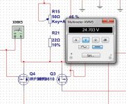
These are now al four who blow this day, she need protection fo as pot opens see picture of sim.
AS I see it do leak from the circlotron back through irf96120 source drain diode to ltp making a 24 volts over the gate and blow it, a mosfet without a diode on source and drain do give not that high leaking voltage, I did see putting a 10 K resistor over the pot and resistor do prevent that leak.
What a pity to discover new things over and over again, so put gate zeners in.
regards
I think I now why because of as the idle pot opens because this do sometimes do jump, getting 24 volts on the gates.
I do not think this need mus current, but blow the mosfets.
These are now al four who blow this day, she need protection fo as pot opens see picture of sim.
AS I see it do leak from the circlotron back through irf96120 source drain diode to ltp making a 24 volts over the gate and blow it, a mosfet without a diode on source and drain do give not that high leaking voltage, I did see putting a 10 K resistor over the pot and resistor do prevent that leak.
What a pity to discover new things over and over again, so put gate zeners in.
regards
Attachments
Last edited:
Hmm after some hours of seeking the fault, I did found that I had put in a irf610 in stead of a 9610 no wonder it did not work.
I have seen with 350 mA of idle, and without a compensator the irf9610 and irf460 combination stay quite stable with the current.
it go up with temp, but very small, however when using 1.3 amp class a you need more precautions because then it will go run faster, here I can use a ntc,, who I have seen do a very wel job and is fast.
regards
Attachments
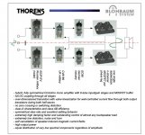
Hi All
I see with this thorens id do use a very big mosfet who has afcouse a big capacitance, but she do drive it with a simple small tube who can NOt give amps, so why do we make such a hassle about driving mosfets gates with class a drivers? I think because the dig mosfets are source followers the capacitance is not such a important issue. I do agree I have now tune my circlotron to 30 mA idle for the drivers making it do a nice square.
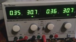
The runout thermally do not occur when use a fan, it idle on 500 mA plus and minus 30 mA. when set the fan off it drops 200 mA when get warm, but after some longer time and if the heatsink is hotter it go up again and run out into amps. So we need to make a compensator who kicks in when the amp get hotter. People who say making a current compensator is a pain in the $#% she are right.
solution for this amp, a lateral mosfet, who I think has a lot better HD also.
regards
I see with this thorens id do use a very big mosfet who has afcouse a big capacitance, but she do drive it with a simple small tube who can NOt give amps, so why do we make such a hassle about driving mosfets gates with class a drivers? I think because the dig mosfets are source followers the capacitance is not such a important issue. I do agree I have now tune my circlotron to 30 mA idle for the drivers making it do a nice square.
The runout thermally do not occur when use a fan, it idle on 500 mA plus and minus 30 mA. when set the fan off it drops 200 mA when get warm, but after some longer time and if the heatsink is hotter it go up again and run out into amps. So we need to make a compensator who kicks in when the amp get hotter. People who say making a current compensator is a pain in the $#% she are right.
solution for this amp, a lateral mosfet, who I think has a lot better HD also.
regards
Attachments
Little movie about the idle run and such.
https://youtu.be/-YB_Ye3l82Q
I have made the circlotron allfet amp working fine, however it do runout thermally, very slowly, first it do get down when warming and later it get up, and when use a fan to cool it run out very fast, the CCS Jfet current source do also help a lot because it is temperature sensitive and need adressed find the temco = 0 working point.
Kees
IMHO to thermally stabilize Circ.OPS ...
-insert appropriate source power resistors for IRF460 ,
- insert two appropriate values NTC resistors , each directly soldered in-between source and gate of each IRF460 , those NTC`s must have very good thermal contact with IRF body`s .
ps , try to replace that thermally unstable JFET-CCS with just single one appropriate value simple resistor and see what`s happen .
Best Regards
- Home
- Amplifiers
- Solid State
- allFET circlotron