It is in Gerber package but I only use online Gerber viewer to check before submitting job to fab house. Good to have either png file or PDF for easy reference. Probably another week before boards get here to US via HK Post. I have to get Sprint or Eagle one of these days. Never did a layout.
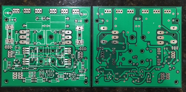

I have zip the stuff so you have a way to stuck the components on it, it is a fault of the pcb maufacturer?.
looks further oke, I think it go to be a nice little circlotron with balls. If we get it stable and working.
When I receive the pcb I get also try it and keep informed, I have experience with this kind of build ups.
regards
looks further oke, I think it go to be a nice little circlotron with balls. If we get it stable and working.
When I receive the pcb I get also try it and keep informed, I have experience with this kind of build ups.
regards
Attachments
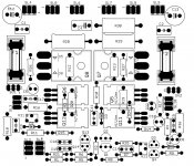
It may be the naming convention of what you called the silk screen or maybe I used an earlier Gerber zip file with bad silkscreen file?
Looks like the references where not on silk, I have check and indeed, the fault is ours,
ehhe, better it is me who did that.
Not a really problem, because we can reference easely with a new silk print.
regards
ehhe, better it is me who did that.
Not a really problem, because we can reference easely with a new silk print.
regards
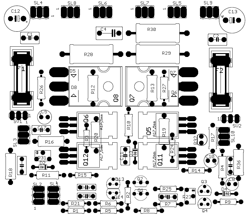

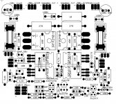
I have done some changes so you can read components better.
regards
regards
Attachments
Last edited:
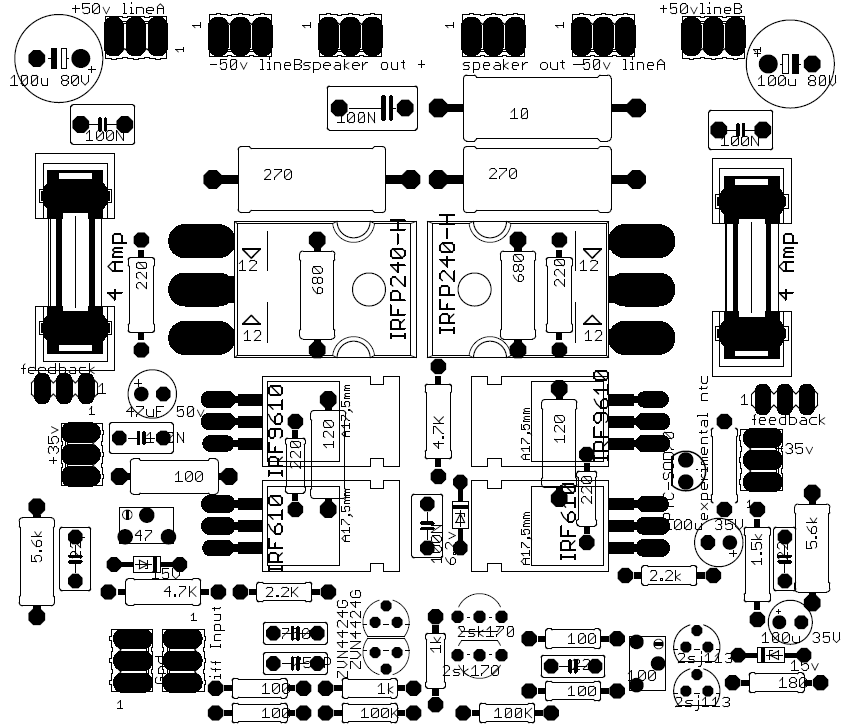
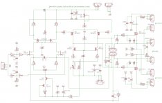
Thanks for new much clearer diagram.
What's difference between line A and line B power supply? Are two psu's needed Orr amp?
What's difference between line A and line B power supply? Are two psu's needed Orr amp?
Last edited:
This is a really interesting amplifier. I always wanted to build one so it is a good opportunity to do it!
This is a really interesting amplifier. I always wanted to build one so it is a good opportunity to do it!
It will be good to have another person attempting to build first unit. Still un tested at this point.
You are missing FH9 from your amp list in signature. 🙂
Just my thought ...
-both zener diodes D2&D3 need some parallel connected bypass cap ,
- OPS ground reference resistors R28&R29 can be with smaller values , 100-150R / 2W .
- maybe I`m wrong but I think that balanced GNFB lines need to be interchanged
All the best !
-both zener diodes D2&D3 need some parallel connected bypass cap ,
- OPS ground reference resistors R28&R29 can be with smaller values , 100-150R / 2W .
- maybe I`m wrong but I think that balanced GNFB lines need to be interchanged
All the best !
Attachments
Thanks for new much clearer diagram.
What's difference between line A and line B power supply? Are two psu's needed Orr amp?
X
The A and B belong to each other, it are two voltages from one transformer as need for a circlotron, but for pcb design I did it this way otherwise it get messy.
so voltage A and A is from same winding.
.
Just my thought ...
-both zener diodes D2&D3 need some parallel connected bypass cap ,
- OPS ground reference resistors R28&R29 can be with smaller values , 100-150R / 2W .
- maybe I`m wrong but I think that balanced GNFB lines need to be interchanged
All the best !
Hi Friend Banat.
Better wether there in belgrade? as I was use to, and nice tomatos who taste nowhere better then there.
Oke, I do not now if for mosfets the zeners will give through the noise she have, with bipolair it does but if it can be measured with modern parts and she sit on source side..
The reference resistors are simulated for higher output voltages, just to be shure it can not burn, can be indeed lower for other demands.
The feedback connections are dependend of fase, I did simulate it this way so it has to be correct otherwise we have a nice transmitter, the jumpers can be used for local feedback, so whe can maybe have tube like sound.
All is simulated, still after that we need to build up step by step because as you now mister murphy can not be simulated.
But I am proud that it is still some small corrections, this you get when not invent the wheel again
have a nice evening.
Not for me because I possible have contrakt this here.
Infection by a bacterium of the genus Borrelia which is transmitted by ticks.
kees
Last edited:
Hi my friend Kees52 !
It is middle of hot summer here , almost as subtropic clima , very hot by day and night with so much afternoon rains and to many moskitos, but is season for nice tasty tomatos for sure,
nice amp project which topic I follow constantly , your design reminds me somehow as is SS variant of Atmasphere OTL Circlotron tube amp topology,
have a nice evening to and wish you to beat those ugly bacterium infection sun as possible .
Hi my friend Kees52 !
It is middle of hot summer here , almost as subtropic clima , very hot by day and night with so much afternoon rains and to many moskitos, but is season for nice tasty tomatos for sure,
nice amp project which topic I follow constantly , your design reminds me somehow as is SS variant of Atmasphere OTL Circlotron tube amp topology,
have a nice evening to and wish you to beat those ugly bacterium infection sun as possible .
I have to seen Baco some day the mother of Marina Stefanovic, such a lady living in centre of belgrade.
Thanks for you nice words, and for the elco on the zeners, I see what happens, I had them in first plans but did read that for mosfet voltage sources it is not needed, and here in the cascode, I do awaiting.
From monday on we get tropical here, above 30 oC, but sometimes then happens this.
Enjoy this beauty of nature, but not for people.
https://www.youtube.com/watch?v=WDFq76pa9mI
back ontopic.
kees
This is a really interesting amplifier. I always wanted to build one so it is a good opportunity to do it!
The more souls the better we here in holland always say.
goodluck.
X
The A and B belong to each other, it are two voltages from one transformer as need for a circlotron, but for pcb design I did it this way otherwise it get messy.
so voltage A and A is from same winding.
.
So to be clear, I will need a quad power supply for two stereo channels? Or in other words, qnty two center tap transformers each with two rectifier/cap banks will be needed? Or can I make qnty 4 rectifier/cap bank PSU's from one large center tap transformer?
Maybe a diagram of PSU and amp would be helpful because I am not clear still what is meant by A and B PSU?
If you look at the schematic you can see how it is.
I go drawn a schematic so you can see how, I think an single transformer with two separate 28 Volts windings will do, you can even took the preamp voltage from it with a regulator who give high separation of such.
I let you now.
regards
Can you let me know the resistor power for the following?
R28-R30 (5 watts?)
R12, R13, R16, R18, R19, R20, R36
R4, R10, R11, R17, R26, R27
The rest of them 1/2 watts?
Thanks
Do
R28-R30 (5 watts?)
R12, R13, R16, R18, R19, R20, R36
R4, R10, R11, R17, R26, R27
The rest of them 1/2 watts?
Thanks
Do
Can you let me know the resistor power for the following?
R28-R30 (5 watts?)
R12, R13, R16, R18, R19, R20, R36
R4, R10, R11, R17, R26, R27
The rest of them 1/2 watts?
Thanks
Do
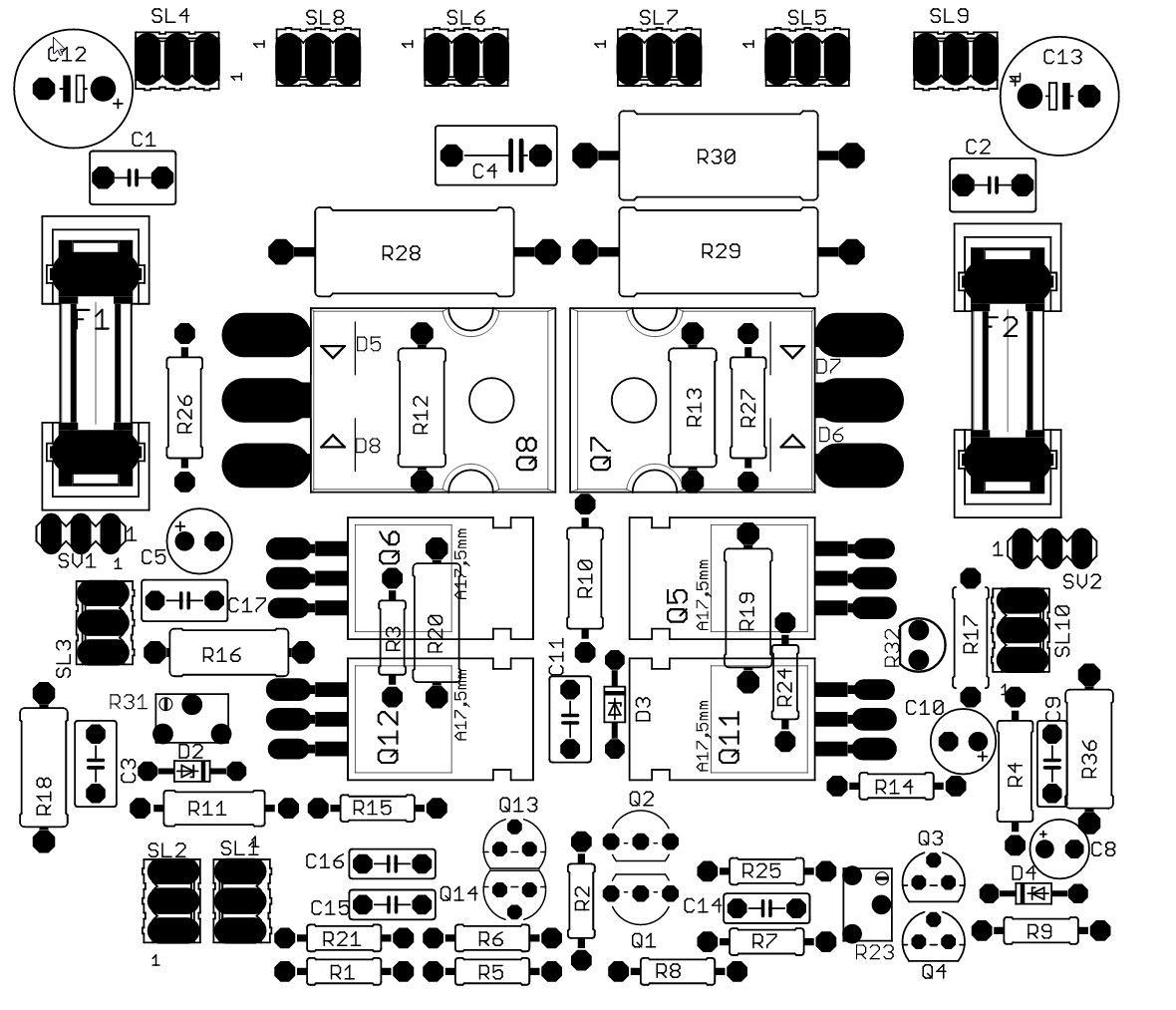
I am going to guess that by the size, smallest is 0.25w, next is 0.5w, next (R12/13/18/19/20/36) are 1w, and big ones are 5w. Probably 3w could work though if one looks at what actual dissipation is.
Last edited:
- Home
- Amplifiers
- Solid State
- allFET circlotron