Kees,
Thanks for that - having a single 50v supply rails is definitely more convenient. Will this work ok for 44v rails? I have a 300va transformer at present that can out this out.
Thanks for that - having a single 50v supply rails is definitely more convenient. Will this work ok for 44v rails? I have a 300va transformer at present that can out this out.
Kees,
Thanks for that - having a single 50v supply rails is definitely more convenient. Will this work ok for 44v rails? I have a 300va transformer at present that can out this out.
Single I do not now, I have need to lift the drivers for the circlotron to work.
Hehe I did found a old quasy amp, with even on 20 mA idle low distortion, however it has voltage feedback I do not like, maybe degeneration resistors will help to get rid of it, but later concers, otherwise we get to much.
I go sim to get other voltages and see the dissipation of the drivers., you need 44 volts? or is this a 32 volts 300vA ac transformer?
regards
Attachments
If the requirement for single 50v rails is difficult don't worry about it. Like I said, another 50VA $11 toroidal trafo and diode bridge and smoothing caps to get 35v rails doesn't cost me too much money or effort really. Many top end amplifiers have separate PSU for the front end - really improves PSRR.
I just happen to have a 300VA 32vac trafo good for about 44v rails at this point that might work.
I also have a SMPS good for 53v rails but limited to 1.4amps continuous current and has peak 4.5amps for 5min and 9amps for 10ms.
I just happen to have a 300VA 32vac trafo good for about 44v rails at this point that might work.
I also have a SMPS good for 53v rails but limited to 1.4amps continuous current and has peak 4.5amps for 5min and 9amps for 10ms.
Last edited:
X
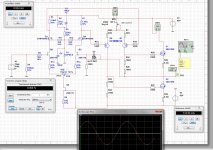
You can use the 44 volts, it sims the same, only some more dissipation in the drivers, but lower the 2.2 k drain resistors a little bring it back, like 1.8k
but you still need to tune the stuff because simulation is not precise enough.
You need the negatie voltage for the Jfet current sources, and for enough swing, but also when implemented it is a nice way to tune for the power semisouth J fets.
32 volts ac give 44 volts dc, 1 amp is enough, but when 5 amp still works but overkill.
the drivers has set themselfs fine with higher voltages, trim the dissipation can be done with that drain resistors, set the idle for the Jfet on input on max
liniarity with the current source resistor first and work from there up.
Your transistors are on the way.
regard
.
Last edited:
If the requirement for single 50v rails is difficult don't worry about it. Like I said, another 50VA $11 toroidal trafo and diode bridge and smoothing caps to get 35v rails doesn't cost me too much money or effort really. Many top end amplifiers have separate PSU for the front end - really improves PSRR.
I just happen to have a 300VA 32vac trafo good for about 44v rails at this point that might work.
I also have a SMPS good for 53v rails but limited to 1.4amps continuous current and has peak 4.5amps for 5min and 9amps for 10ms.
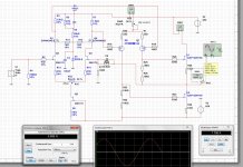
Do you derive the voltages from the power transformer? you need separation and can use voltage regulators for that.
44 volts on the circlotron itselfs do fine. As you say, a small separete transformer is nice.
You say about the smps, I busy with a welding smps, 150 amps, but that is a whole other story not told here.
Attachments
Last edited:
Thanks for running that at 44v Kees. Do the sims show similar performance from harmonic distortion etc?
If I can run all from same 44v rail that would be most convenient.
If I can run all from same 44v rail that would be most convenient.
Thanks for running that at 44v Kees. Do the sims show similar performance from harmonic distortion etc?
If I can run all from same 44v rail that would be most convenient.
Distortion is not affected only max power.
regards
IRFP250M;ZVN4424;J113 Mouser
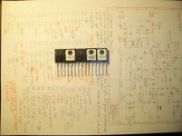
Hi kees and x.
The Hexfet, if from one charge are in near same Vgs~ 4,2V
You don't should buy from allweit- much overpriced!
http://www.mouser.de/ProductDetail/...EpiMZZMshyDBzk1/Wi5%2bqVgN3%2bWS8tlzNeBliYSs=
This part are also produced in China now- who the most..... our workbench 😀.
A very nice designt Ampboard.
Some pics of my HexFet.
You can see different Vgs Vishay/IR parts- measured on 15VDC Tester.
Cheers Bangla.
Attachments
Hi kees and x.
The Hexfet, if from one charge are in near same Vgs~ 4,2V
You don't should buy from allweit- much overpriced!
http://www.mouser.de/ProductDetail/...EpiMZZMshyDBzk1/Wi5%2bqVgN3%2bWS8tlzNeBliYSs=
This part are also produced in China now- who the most..... our workbench 😀.
A very nice designt Ampboard.
Some pics of my HexFet.
You can see different Vgs Vishay/IR parts- measured on 15VDC Tester.
Cheers Bangla.
Thanks for the input.
I have seen on ebay a tester so we can adjust things more easy.
Component Tester Transistor Diode Capacitor ESR Meter MOSFET NPN PNP Inductor | eBay
for that mony we can not make one ourselfs.
The schematic you post is a single ended one? with a current source on one side driven by signal to follow the mosfet amplitude?. I do
now these, but I do not use bipolairs.
.
regards
Last edited:
X
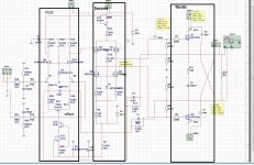
If you setup like this and take attention of gate on voltages it will get oke.
solder the first section, adjust, then second and thirth.
Bu maybe you have own system, I do it like this and use a adjustable supply 0 to 80 volts 500 mA, double voltages it has.
regards
If you setup like this and take attention of gate on voltages it will get oke.
solder the first section, adjust, then second and thirth.
Bu maybe you have own system, I do it like this and use a adjustable supply 0 to 80 volts 500 mA, double voltages it has.
regards
Attachments
You mean assemble in 3 stages and test as I go to ensure each section works before moving to next? Good idea.
If you can show same delineation on actual PCB layout, that would be helpful.
Thanks.
If you can show same delineation on actual PCB layout, that would be helpful.
Thanks.
You mean assemble in 3 stages and test as I go to ensure each section works before moving to next? Good idea.
If you can show same delineation on actual PCB layout, that would be helpful.
Thanks.
X
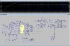
Yes that is what I mean, just do destignator of components as use for build up in stages. like R1 R2 etc.
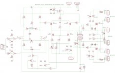
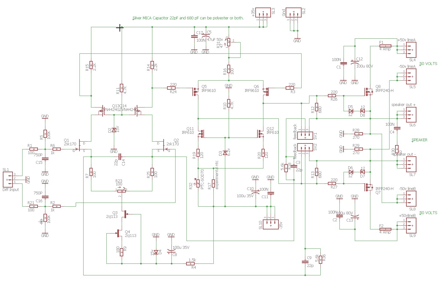
Have a cleaned up schematic and board for clarity
regards
Attachments
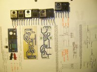
Hi Kees and X.
1x470µ max35v same a second 1000µ and a bridge rectifier some screw terminal and
3 pins to change direction N-P-Type GS connection. A single 15VAC you could find anywhere.
I have bought a different Diode Tester- works with 9V block accu- so you have lower
measured reference Vgs that's the little difference than.
The right pic shows us the not real finished Ranchu- Hugh Quasi Amp- X knows what it
means better than any others.
I follow here.
Cheers Bangla.
In left picture is shown the tester. It needs only L7815 + heat sink 3x470R 1-2W resistorfor that mony we can not make one ourselfs
1x470µ max35v same a second 1000µ and a bridge rectifier some screw terminal and
3 pins to change direction N-P-Type GS connection. A single 15VAC you could find anywhere.
I have bought a different Diode Tester- works with 9V block accu- so you have lower
measured reference Vgs that's the little difference than.
The right pic shows us the not real finished Ranchu- Hugh Quasi Amp- X knows what it
means better than any others.
I follow here.
Cheers Bangla.
BanglaH,
Can you please share the schematic and the PCB pdf? I could make this PCB with nail polish on copper foil boards a la Uncle Charlie. 🙂
Can you please share the schematic and the PCB pdf? I could make this PCB with nail polish on copper foil boards a la Uncle Charlie. 🙂
saque.de
Hi X.
Sorry i have no PDF, but there is a contact to Volker webmaster@saque.de- German Diy'er.
I only can send pictures, but better link to his page.
Mosfets
Here you will find all who it works and needed parts- speaks international by
viewing pics. 😀 😉,hopefully it works?
I have build it on breadboard.
Cheers Bangla.
Point to point on perfboard would be fine for this purpose. Thanks.

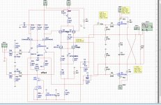
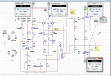
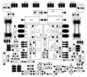
This is really helpful - I have not seen the top screen parts placement view until now.
Was this not in the plot output? has to be there.
Have the value removed and keep destinators so it is less messy as eagle pretent to do.
SV1 and SV2 are connectors like in a pc with a jumper, here you can choose for local or full feedback, for as you not now
because I did not mention it also.
regards.
Last edited:
- Home
- Amplifiers
- Solid State
- allFET circlotron