Again, because sometimes text is just gone here when go advanced.
I have searchs for hours to find why the ltspice did not work and multisim did.
So people, I am curious you also find it and more quicly then me, and X maybe you?.
Looks very nice. I like the symmetry. Which one is temp compensator ?
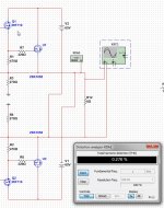
C15 should be picoF.
I have now look at it in multisim, also here when switch the jfets drain source do give no change both do work the same in output.
We now why, because connecting wrong will give trouble in real live..
Did drawn a quick amp with jfet, also here connecting drain source however side, give same actions, so it is program who see this? special for the J fets or something, can someone clear this>?
I need clear about if before I go on with pcb, because do things for nothing I do not like.
regards
JFET works like a variable resistor so probably why works either way.
Hi X
I have play a little with Tina, I have never seen such buggy software is this one.
I get it not to work, gives errors, while ltspice and multisim works fine.
making wires it jumps all the way with it, and the screen flikker a lot.
No not my software, For the Jfets, this is the first thing a now, so you can in a amp switch them with the voltages and not destroy them like a normal mosfet?.
IN ltspice I did get it not to work, the old one did fine, so it is a gess whatt happens, maybe I make a test pcb and go find out.
regards
Attachments
Tina is tricky with connections. Double check your wire connect points. Sometimes it looks like it is connected but actually open circuit.
I have play with it, it is not mine software, very troublesome in compare with multisim, these is such a easy software with yes also his points, and much parts, but less supported and this a pity.
LTspice get the amp not working, get trouble distorted output, high current and stuff, maybe because of the models there.
multiim do right, but has the jfets in it,s librarys.
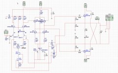
here the schematic from tina, I did the company version, a old one so it can maybe not loaded.
Can you play also with it.
kees
LTspice get the amp not working, get trouble distorted output, high current and stuff, maybe because of the models there.
multiim do right, but has the jfets in it,s librarys.
here the schematic from tina, I did the company version, a old one so it can maybe not loaded.
Can you play also with it.
kees
Attachments
I have play with it, it is not mine software, very troublesome in compare with multisim, these is such a easy software with yes also his points, and much parts, but less supported and this a pity.
LTspice get the amp not working, get trouble distorted output, high current and stuff, maybe because of the models there.
multiim do right, but has the jfets in it,s librarys.
here the schematic from tina, I did the company version, a old one so it can maybe not loaded.
Can you play also with it.
kees
Can you send Tina file as well?
I did see with again a other approach I get with current feedback a la strange way, very width respons, to 1 Mhz without cap correction, this we need to remove overshoot who give a image how it sounds anyway. Distortion is with 80 Volts output (peak), did drop to 0.009 with a cascoded cuurrent source for long tail J fet input.
Attachments

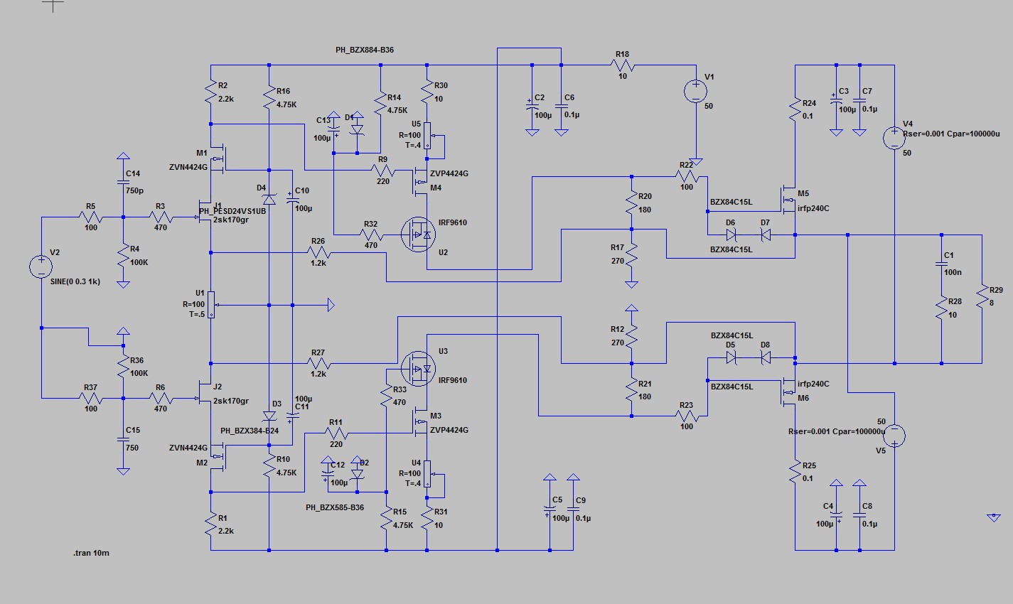
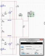
Look at the output, it is 100 Volts peak, and have with one circlotron a la mirror 0.005 % distortion, when do the regular circlotron not mirroring I get 0.25 %
You may say why, I think the mirroring cancel distortion out a better way then regular. see I have a extra mosfet in it as driver also, don't forget it give much lower input capacitance and you can parallel more mosfets.
regards
You may say why, I think the mirroring cancel distortion out a better way then regular. see I have a extra mosfet in it as driver also, don't forget it give much lower input capacitance and you can parallel more mosfets.
regards
Attachments
Hi Kees,
Nice find with mirroring - makes sense like push-pull speaker drivers cancel even order distortion. I see you are back to lateral FETs. Have you given up on good but cheap IRFP240? I like ability to parallel more outputs.
Where is the extra driver you mention? I don't see it.
Nice find with mirroring - makes sense like push-pull speaker drivers cancel even order distortion. I see you are back to lateral FETs. Have you given up on good but cheap IRFP240? I like ability to parallel more outputs.
Where is the extra driver you mention? I don't see it.
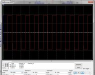
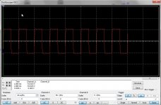
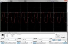
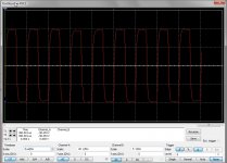
Here are the square waves on 500Khz, 200Khz, 100Khz, and 20Khz.
We need to limit that bandwidth because of overshoots, here there are not because I have caps used in feedback, voltage feedback here.
You now we use mosfets who are capacitive devices and love overshoot who will damage the sound.
next is the current feedback version test.
We need to limit that bandwidth because of overshoots, here there are not because I have caps used in feedback, voltage feedback here.
You now we use mosfets who are capacitive devices and love overshoot who will damage the sound.
next is the current feedback version test.
Attachments

Last edited:
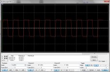
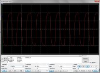
Now the current feedbacked one.
20Khz, 100Khz, 500Khz bandwidth looks some smaller with current feedback who
is because of caps for stability and overshoot.
I limit the amp because it is better for the sound, high slew rate is not always a
way to get good audio, it has to get th 100Khz is enough, cap in feedback can be
afcouse adjusted.
Attachments
Last edited:
Hi Kees,
Nice find with mirroring - makes sense like push-pull speaker drivers cancel even order distortion. I see you are back to lateral FETs. Have you given up on good but cheap IRFP240? I like ability to parallel more outputs.
Where is the extra driver you mention? I don't see it.
Hi X
No the laterals just was here, I can also use the others, I go sims these also, thanks for the find, I even has not see it.
I use laterals in the hybrid here in home, I do like them, also it is more easy to get them working because of higher vg on.
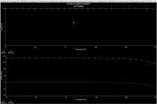
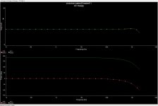
here are the frequency plots. first current feedback and second voltage. caps disconnected.
regards
Attachments

Looking at the square waves it would seem that the voltage feedback looks superior at 200khz. What is the advantage of current feedback if it doesn't look as clean of a squarewave?
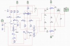
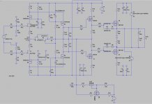
I have just remove again two mosfets, not needed in vertical mosfet, it has 80 volts peak to peak 0.009% 1 Khz, and 0.035% 20 Khz, 0.134% 100Khz. Current feedback.
when put feedback on gates of Jfets, makes voltage feedback I get with 80 volts peak to peak output.
1 Khz, 0.001%, 20 Khz 0.018% 100 Khz 0,120%
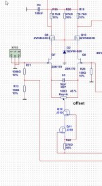
Here schematics, and now I go relax, and into the forrest enjoy nature because I have need some rest. enough combining of topologies.
This is the most simpel one I get, the other one has only local feedback, but it is a more complicated schematic, these two can has also local feedback, from the drivers let the power mosfet without feedback,the single ended aproach I like more the balanced who do affect only even harminics but noth the oneven ones who are not good for good sound, it get harsh. long tail fase splitter has the best effect I think.
when put feedback on gates of Jfets, makes voltage feedback I get with 80 volts peak to peak output.
1 Khz, 0.001%, 20 Khz 0.018% 100 Khz 0,120%
Here schematics, and now I go relax, and into the forrest enjoy nature because I have need some rest. enough combining of topologies.
This is the most simpel one I get, the other one has only local feedback, but it is a more complicated schematic, these two can has also local feedback, from the drivers let the power mosfet without feedback,the single ended aproach I like more the balanced who do affect only even harminics but noth the oneven ones who are not good for good sound, it get harsh. long tail fase splitter has the best effect I think.
Attachments
Last edited:
Thanks, Kees. Looking good.
Are you sure we can run 65v supply rails to one pair of IRFP240? I guess I heard Apex said he runs his on 70v rails... kind of scary 🙂
But 0.001% THD at 80v p-p is very good.
Have fun in the forrest.
Are you sure we can run 65v supply rails to one pair of IRFP240? I guess I heard Apex said he runs his on 70v rails... kind of scary 🙂
But 0.001% THD at 80v p-p is very good.
Have fun in the forrest.
Hi X
I have lower the voltages to 50 volts, the supply I mostly use, the irfp is quite rugged, do not blow easely, the fuse go first.
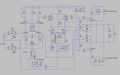
these schematic I go make pcb for, it has need some extra parts like cap,s and connectors but go do this is eagle afcouse.
other nice outcome is the current runaway is corrected within the drivers. looks quite good.
the voltage feedback version I do not make, it has offset problems, this because I need two feedbacks as it is balanced this can only through the sources of the jfets who are already mirrors., it can be done but need then a double version, makes more parts, plus I like current feedback more then voltage, I like feedback not att all but is needed with mosfets or bipolairs the most of time.
I stick with the current feedback, and maybe we need a servo, but we wait what it does.
regards.
kees
I have lower the voltages to 50 volts, the supply I mostly use, the irfp is quite rugged, do not blow easely, the fuse go first.
these schematic I go make pcb for, it has need some extra parts like cap,s and connectors but go do this is eagle afcouse.
other nice outcome is the current runaway is corrected within the drivers. looks quite good.
the voltage feedback version I do not make, it has offset problems, this because I need two feedbacks as it is balanced this can only through the sources of the jfets who are already mirrors., it can be done but need then a double version, makes more parts, plus I like current feedback more then voltage, I like feedback not att all but is needed with mosfets or bipolairs the most of time.
I stick with the current feedback, and maybe we need a servo, but we wait what it does.
regards.
kees
Attachments

Hi Kees,
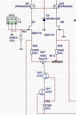
Nice work - looks great. Can we replace D2 zener wtih qnty 4 blue LED's plus one red LED in series? That gets about 15.4v and is less noisy than zener switching noise (so I am told). You will need to change R20 to maybe 6.8k.
50v is a good rail voltage. Glad you got rid of that secondary voltage requirement.
Which component is serving as the temperature compensator? The diode D1?
Hi Kees,
Nice work - looks great. Can we replace D2 zener wtih qnty 4 blue LED's plus one red LED in series? That gets about 15.4v and is less noisy than zener switching noise (so I am told). You will need to change R20 to maybe 6.8k.
50v is a good rail voltage. Glad you got rid of that secondary voltage requirement.
Which component is serving as the temperature compensator? The diode D1?
X
The place where the zener is do not have impact, it is in the current loop, that give no problems, so much led's it makes it a disco. the other zeners in gates also give no problems, she are properly bridged with a capacitor remove any noise, mosfets are less prone to it also, bjt has more trouble.
The VAS in these amp has lucky me, a nice correction so as I see no need for compensation, but I do keep account, it will be a ntc.
I drawn the eagle schematic and go make a pcb and test it, you want smt/.
regards
Now we can go on, I have two possible tryouts, one with feedback and one with local feedback, that will give maybe some tube like sound.
I go do first the current feedbacked one.
Both sim wel in all simulation softwares
regards
I go do first the current feedbacked one.
Both sim wel in all simulation softwares
regards
Attachments

- Home
- Amplifiers
- Solid State
- allFET circlotron