
You might look at one used on the VHex amp - getting the resistances and the pot value right is critical. Also, an LED was used to reduce temperature sensitivity. It requires a BJT by that's ok as it is out of signal path.
http://www.diyaudio.com/forums/solid-state/286992-irfp240-9240-amplifier-simulated-tina-18.html
http://www.diyaudio.com/forums/solid-state/286992-irfp240-9240-amplifier-simulated-tina-18.html
You might look at one used on the VHex amp - getting the resistances and the pot value right is critical. Also, an LED was used to reduce temperature sensitivity. It requires a BJT by that's ok as it is out of signal path.
http://www.diyaudio.com/forums/solid-state/286992-irfp240-9240-amplifier-simulated-tina-18.html
X
Need a darlington transistor, a higher loop do work, however now it is to much.
but it works, in sim, so do not now real live effect.
last photo is a darlington, it is more sensitive so better regulation, now I have only put a resistor in emitor to let it work, no diodes please because later on I have to put in gate protectuion diodes who is the last work,before pcb.
regards
regards
Attachments

Oke again, like laurel and hardy always says, when you don't succed the first time, try try again.
Maybe I call it the Hardy amp, or Laurel amp..
First picture without a multiplier, second with a bjt darlington transistor, we need high beta,s here?,.
The emittor degeneration resistor did the trick, see previous post where overcompensation occur, quite precise work, just couple hunderd millivolts do much.
I am happy that it can work this way, the negative supply however is also critical I did see, with change it I can now in the fornt end use all kinds of fets, even Jfets with more then -12 volts on voltage or +12 volts, just by change the negative voltage, nice stuff.
Please be aware the temp drift is for whole amp, who has same temperature in simulation, can not change much.
One negative point, windows 10 do let crash multisim more then often, and have lost today just 52 times the data. Or multisim is a quite buggy program, but interactive is very nice to work with.
regards
regards
regards
Attachments

Last edited:
Nice work on the temperature compensation. Are you sure you need a Darlington? I think Vzaichenko used a MJE340 here and added a LED to reduce its sensitivity. I have BD675 Darlington that is TO126 so perfect size for temp compensator.
Hi X
I have now using a mje340 transistor and tryed a mosfet version, the transistor better, because we have to do correction on a double fashion, I have one multiplier and do adjust both circlotron halves in one go, I get som rising when put 400 mA of idle, going up to 600 and stay there to 80 oC degree then drops quite fast, but think this is because of sim, also it sim the whole amp, we need to experient with it. Going laterals afcouse do work without trouble, just a resistor pot for idle suffice.
now I think we close to a pcb, this weekend I go start with it because I am curious about it, do even think that we can put it also otherways, making it a whole part of circlotron, you here about it..
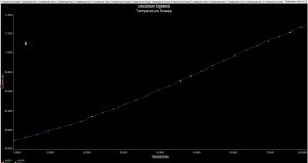
Picture 1 is the run away graph, you see it do go fast to destruction.
regards
Attachments
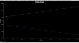
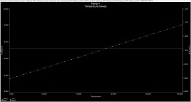
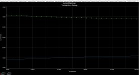
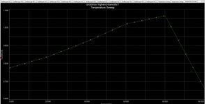
I did now temp sweep, do now it is the whole amp, we have to test the vbe multiplier, it is some strange way we use it, constant voltage source, the negative voltage there is important it is stable, changing this allow however for use a kind of fets, J-fets van Semisouth, even the infinion -12 volts on, or igbt's.
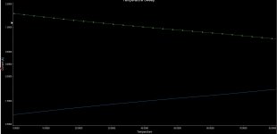
the sweep is with class ab, and class a, I think this is fine, the irfp mosfets do when get 80 oC loose idle current, but so hot we gonna not use afcourse.
picture 1 600 mA idle setup, picture 2 1.5 amp idle current. both stay nice where she need to be.
the sweep is with class ab, and class a, I think this is fine, the irfp mosfets do when get 80 oC loose idle current, but so hot we gonna not use afcourse.
picture 1 600 mA idle setup, picture 2 1.5 amp idle current. both stay nice where she need to be.
Attachments

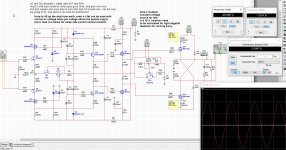
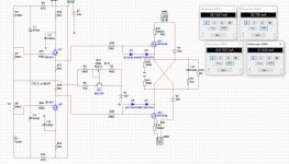
I need some advise, I have put parts out of the amp who are on heatsink, because otherwise the whole amp is used in sim, now I have done this things get more accurate.
I have done use diodes, also a transistor as diode but give overcompensation, a mosfet as a diode maybe.
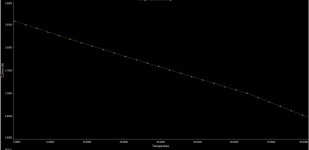
The 1n4148 diode do well, keeping it within plus minus 50 mA over 0 to 100 oC.
some advise who other will tackle this I do like, or if I have done this now better then before, I think this is more stable, using two pots in gates of driver and a diode in netagive voltage line where go 150 mA and more when fullpower driving so 1n4148 is small, A diode in series with pot,s is maybe a option. Picture one is without, you see a run away, last is with diode it is a lot better, two diodes dit overcompensate, or we can use a Thermistor in series, one with low resistance.
Thanks for the advise.
regards
I have done use diodes, also a transistor as diode but give overcompensation, a mosfet as a diode maybe.
The 1n4148 diode do well, keeping it within plus minus 50 mA over 0 to 100 oC.
some advise who other will tackle this I do like, or if I have done this now better then before, I think this is more stable, using two pots in gates of driver and a diode in netagive voltage line where go 150 mA and more when fullpower driving so 1n4148 is small, A diode in series with pot,s is maybe a option. Picture one is without, you see a run away, last is with diode it is a lot better, two diodes dit overcompensate, or we can use a Thermistor in series, one with low resistance.
Thanks for the advise.
regards
Attachments

Last edited:
Thanks for the due diligence Kees. I don't quite follow you now but I assume you are making these changes to get better stability. I'm not sure why an MJE340/50 can't be used? They are used on other IRFP240 amps successfully. I have also used even BD139 with a pot and two resistors for the temperature compensation on the FH9? If all this is too difficult maybe we go back to lateral FET? I like how low distortion IRFP240 can be when operating in class A.
Thanks for the due diligence Kees. I don't quite follow you now but I assume you are making these changes to get better stability. I'm not sure why an MJE340/50 can't be used? They are used on other IRFP240 amps successfully. I have also used even BD139 with a pot and two resistors for the temperature compensation on the FH9? If all this is too difficult maybe we go back to lateral FET? I like how low distortion IRFP240 can be when operating in class A.
Hi X
You forget this is quite different, the vbe sit between negatief supply on a strange manner, I did not yet see that, it is very sensitive because the voltage over it and the drivers current he do have to cope with, that is why I do try now if I can use the driver gates and insert a simple diode in the negative supply.
I do test still, so I do find a cure, we can go lateral, but I can not stand why not verticals, this amp can take all when ready also SIC J-fets.
But nicely multisim do work again, the NOD32 virus scanner did interact with it, letting it crash or slowdown, I have more software who is removed by this scanner, not good,.
regards
X,
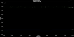
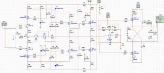
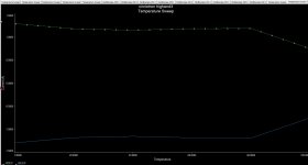
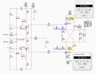
I think we are there, a pnp transistor was the saving, now the emitter sits on th amp side, giving low impedance, that was need a low impedance version of such, but it do work, however when go high idle current it go do still loose some tracking, however when do 500 mA it is one straight line.
So we can go pcb at last.
As seen on the last pic, when I sim the whole amp, what means everything gets 100 oC max, it go wrong, but heee, it is not the way we do that, only driver, vbe multiplier and output mosfets are thermal coupled through heatsink.
and we need experiment X, the multipier is low impedance, and pnp, it do work the best, just to pnp why not thinking earlier about that.
regards
Attachments

Last edited:
Looks good. Are we on symmetric rail supplies now? How many volts? +/-35v?
Ehh X if you look good it was always symmetric, excist a circlotron with only one single rail? if you look at the posts you see that, only the negaive rail of the front end has in my case two different voltages, however it is corrected, you need 2x 35 volts and 2 x 50 volts for the circlotron itselfs, it is the only way as far I do now.
The negative for the front end is needed for the bias, to get where i want, so I can put everything in, al kinds of mosfets, normally on or off...
regards
- Home
- Amplifiers
- Solid State
- allFET circlotron