I have test the mosfets on a batterie, drawing 20 amps, get warm, but not much other problems, this do not mean it are not fakes, because it can also be other mosfets, I go try high voltage also, and not in the amp and see when it go get trouble.
I have tube supplys so making a boom is easy.
It are mosfets that is for shure.
I have tube supplys so making a boom is easy.
It are mosfets that is for shure.
X
These are proberly igbt,s and not mosfets, because measure as such.
that is why the current is oke, igbt's are quite strong
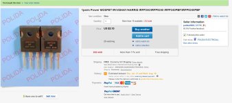
That ebay do so little to remove such people. I go watch them in future and go try and send these back.
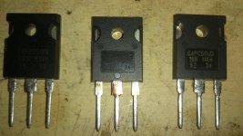
The irfp240 are also not to be trusted because also these looks igbt's because a real mosfet go to short circuit when measure with a normal ohm meter and switch the pins. The back of these irfp 240 is also corroded.
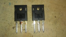
I do not take any risc, the right ones on the photo are igbt's for a smps welder are 50 amps and 800 volts, do look normal.
regards
These are proberly igbt,s and not mosfets, because measure as such.
that is why the current is oke, igbt's are quite strong
That ebay do so little to remove such people. I go watch them in future and go try and send these back.
The irfp240 are also not to be trusted because also these looks igbt's because a real mosfet go to short circuit when measure with a normal ohm meter and switch the pins. The back of these irfp 240 is also corroded.
I do not take any risc, the right ones on the photo are igbt's for a smps welder are 50 amps and 800 volts, do look normal.
regards
Attachments
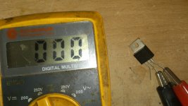
My MOSFETs measure 17Mohm either way between pins. Wow - so these are IGBT's relabeled as MOSFETs ?
My MOSFETs measure 17Mohm either way between pins. Wow - so these are IGBT's relabeled as MOSFETs ?
I have a small mosfet measured, on the picture of the seller, this name is not very trustable. as you see on last phot is what I get, I miss some production numbers as seen on middle photo, so also these go back.
measuring give a readout of many ohms when on, what means it is igbt these witch never total on with these measurement need a special test schematic...
Go make two, I am curious now. put high amps and voltages until it blows, then I now.
But Oke, offtopic again.
regards
kees
Attachments
Last edited:
Did some more tests.
car bulp 50 watts, on 12 volts battery.
the irfp240 full on give a 1.8 volts between S and D with 4 amps, mosfet get hot and then lamp go dimming total, after cool down mosfet it works again.
the irfp9240 same problem.
the small original mosfet 50 amps when on 1.2 volts get warm not to hot.
the irfp240 who I have get past week, when fully on get 5.2 volts between S an D getting fast very hot and stops conducting, after cooling down it works again.
the IGBT G4PC50UD 800 volts 27 amp get 4.7 volts between E and C and get hot.
I did not use a heatsink.
conclusion can be the irfp are igbt,s.
regards
Measure the capacitance of the Supply and Gate and compare to known MOSFET. Need to run power tests with heatsink.
Measure the capacitance of the Supply and Gate and compare to known MOSFET. Need to run power tests with heatsink.
I think you can not meaure the gate capacity just with a normal capacitance meter. However a genuin mosfet did measure 3,79 nano while it has to be 3,9 nano so it is quite close.
the other are all way to high, irfp has 1300 pF and these have 3700 pF, so looks a little as igbt, if it get warm it has lateral effect also, the good fet do when warm dorp get,s lower, that is oke.
regards

Those actually look real. Similar to the ones I got on Aliexpress. The fine satin finish on the pins and metal tab are sort of indicative of a genuine item as is the sharp detail on the epoxy molding of the main body. Price seems about right too.
Those actually look real. Similar to the ones I got on Aliexpress. The fine satin finish on the pins and metal tab are sort of indicative of a genuine item as is the sharp detail on the epoxy molding of the main body. Price seems about right too.
These are from aliexpress.
I have be a member now, and order them.
for the send irp250n I have, are reprinted ones, the capacitance is 7.9 nF while the original ones hasd 1.3 nF in datasheet. when fully on she got hot, and that means it is a lateral or it is a igbt, because a irfp 250 has a on risistance of 0.085 ohm means a half watt when put 5 amps through, I did sned 3 amps through and it get very hot very fast.
the other original one has also low on resistance and get quite warm, think 60 degree, and no further problems, it was a to220 mosfet.
regards
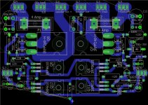
I am further with the pcb, step by step because it needs thinking and it is a art I not yet have compleet in my hands, there are guys who do better.
I did discover that the smt components are ruled out slowly, only some remains, because she give a ugly board where is as a forrest no trees.
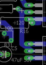
Sometimes eagle make a mess without asking see picture two.
The lighted pads are the ground connections, I keep on edge,
regards
I did discover that the smt components are ruled out slowly, only some remains, because she give a ugly board where is as a forrest no trees.
Sometimes eagle make a mess without asking see picture two.
The lighted pads are the ground connections, I keep on edge,
regards
Attachments
Last edited:
Will IPS fit on the same board or two separate boards with header pins/jumpers?
Looks nice so far.
Looks nice so far.
Will IPS fit on the same board or two separate boards with header pins/jumpers?
Looks nice so far.
All come on one board, it is that I do try that.
it is some more wide, 2 a 5 mm.
regards
Will IPS fit on the same board or two separate boards with header pins/jumpers?
Looks nice so far.
If you mean ips is the power supply these are not on the board, it is quit here, people think it will not work?,
regards
No IPS is input stage - all the preamp stuff with small signal transistors before the power stage.
Not sure why it's been so quiet in this thread - you need to get a layout posted for people to really see that this is a real circuit.
Not sure why it's been so quiet in this thread - you need to get a layout posted for people to really see that this is a real circuit.
Dit see these ones on aliexpress, looks there are better sellers?.
regards
I think these are fakes.
I think these are fakes.
I think you look also to the letters on the print, looks a little thick, normal she are laser printed I did hear.
If you now sellers who are trustable let me now, maybe there is al a thread about this.
No IPS is input stage - all the preamp stuff with small signal transistors before the power stage.
Not sure why it's been so quiet in this thread - you need to get a layout posted for people to really see that this is a real circuit.
X
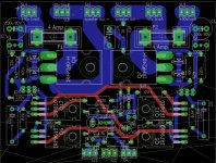
I do now I not always are very fast, oke, I have tryed some pcb outlines, I have to say
without double side I can not get a nice compact board, this is the thirth attempt, if these
also failes because of to long lines I put transistors in edge, like most have.
but it looks that I get somewhere now, the double feedback lines are also importent, needs close
to speaker connection.
tomorrow the last part,if it fail, I start over, yes X, pcb making is a real art, like a painter, and and I'ts not me.
X also I can not put the transistors in one line, because things work out wrong.
regards
Attachments
I am good with double sided board. Same cost as single sided for me.
Thanks find the work on the design. It's starting g to look like a real amp!
🙂
Thanks find the work on the design. It's starting g to look like a real amp!
🙂
- Home
- Amplifiers
- Solid State
- allFET circlotron