The eagle do also miss traces, when I was amost done suddenly traces are gone and such things, not very trustable software.
Hi I use eagle extensively. I never found any problem of missing traces. Just check to see if software is corrupted or infected. Unless I make a mistake in schematic, never have eagle produced a bad connection/ missing connection. I dont even bother manually checking the layout against schematic, still get perfect working PCBs.

reg
Prasi
But I don't see you using Eagle for analog power amps. Is it because with power amps it's more about knowledge of best practices for layout? So Sprint works well for that?
X
My design is make form different already excistent topologies, the amp is a single ended preamp version only the circlotron is balanced, I have a balanced version though, and these is more easy to pakeb pcb of, the F11/12 has p an n transistors so it works always out nicely.
regards
My design is make form different already excistent topologies, the amp is a single ended preamp version only the circlotron is balanced, I have a balanced version though, and these is more easy to pakeb pcb of, the F11/12 has p an n transistors so it works always out nicely.
regards
But I don't see you using Eagle for analog power amps. Is it because with power amps it's more about knowledge of best practices for layout? So Sprint works well for that?
But I don't see you using Eagle for analog power amps. Is it because with power amps it's more about knowledge of best practices for layout? So Sprint works well for that?
It do not matter what you use, I like to use programs who do check things.
I do not like eagle this time, I have made some polygons and it connect to each other, or move traces on his own.
I use professional pcb software because it check lost connections, I do over to diptrace when this one is done, eagle looks very good on graphics way but has such strange behavior is compare to others.
tomorrow things are ready, and if people now why eagle do work such rare way I like to now.
regards
Attachments
It's really taking shape and looking good Kees. Nice job!
Yes but only as you see on picture one and two on previous post, the polygons even when coupled to two different nets it still connect to everything. I did make poligons for the parts where current flows and connection to these nets, however eagle do not right making shorts.
I do need to find a way to prevent this.
regsr
if you share the file with I can try to understand whats going on and may be try to find a solution.
reg
prasi
Last edited:
Yes but only as you see on picture one and two on previous post, the polygons even when coupled to two different nets it still connect to everything. I did make poligons for the parts where current flows and connection to these nets, however eagle do not right making shorts.
I do need to find a way to prevent this.
regsr
This was a eagle error after I did search I need give them ranks, now it works
that was also the trouble I did mention off, eagle looks good graphically but diptrace do better and more easy, errors are ruled out with it..
X
I have now make gerber, but only test and postscript, so you can see how it looks, when you need changes in pads or components you need to tell me and with the dimensions given. And the kind of gerber what you need and maybe drill files.
The caps where sound go through are silver mica, these do fit.
I do go as last action check the mosfet pinouts if these are right now this evening.
regards
Attachments
if you share the file with I can try to understand whats going on and may be try to find a solution.
reg
prasi
Hi Prasi
Did find it, I need to rank them, like 1, 2, 3 etc.
then it do work for me, eagle needs to be told everything, it is a minus.
regards
Attachments
Hi Kees,
Looks very nice. The size appears to be 103mm though - can you please trim to 100mm max? Also, it seems we are back to a dual voltage supply now with 50v rails and 35v rails? 35v is just for the VAS is that right? So what is max current needed? I can probably make a regulated shunt supply from main 50v supply if under 1amp.
Looks very nice. The size appears to be 103mm though - can you please trim to 100mm max? Also, it seems we are back to a dual voltage supply now with 50v rails and 35v rails? 35v is just for the VAS is that right? So what is max current needed? I can probably make a regulated shunt supply from main 50v supply if under 1amp.
Hi Prasi
Did find it, I need to rank them, like 1, 2, 3 etc.
then it do work for me, eagle needs to be told everything, it is a minus.
regards
Hi,
I was suspecting the same thing🙂. Just run DRC (in layout) / (ERC in schematic) when in doubt, you will get a bunch of errors, then you try to resolve them. If you are stuck, google for that particular error, you will be sure to get a solution somewhere. There are plus and minus of each and every software, biggest advantage of eagle is backward compatibility with schematic+ you cant delete any component / traces in layout. Its a sure thing to get working PCB. Just ratsnest once so that there are no airwires and then run ERC and DRC once you are about to generate gerbers so that there is no accidental mistake.
reg
Prasi
Last edited:
I have errors like drill, but these are not a problem, sometimes I see also the hole in a part who do give clearance errors but also not a problem when you now why and stuff.
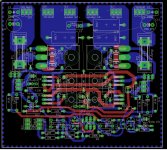
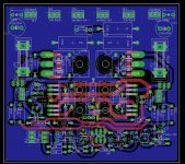
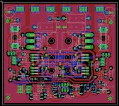
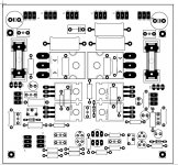
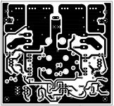
have X squeeze the circolotron amp in a double sided 100 x 100 mm as you ask, I did need to put transistors closer to each other and change some more things.
I think it looks nice, I have keep a big ground and short connections, I ask give a sign when need some different part. And I need to now what kind of output you want for the pcb making, like gerber and drill files.
For the supply it is a power amp you need some more then one amp and 50 volts, look at peaks of 10 amps if you get loud, the preamp has plus and minus 35 volts and need 500 mA or better 1 amp if you have, both work last has more beefy capacitance driving.
regards
Attachments


Last edited:
Hi,
I was suspecting the same thing🙂. Just run DRC (in layout) / (ERC in schematic) when in doubt, you will get a bunch of errors, then you try to resolve them. If you are stuck, google for that particular error, you will be sure to get a solution somewhere. There are plus and minus of each and every software, biggest advantage of eagle is backward compatibility with schematic+ you cant delete any component / traces in layout. Its a sure thing to get working PCB. Just ratsnest once so that there are no airwires and then run ERC and DRC once you are about to generate gerbers so that there is no accidental mistake.
reg
Prasi
If you do drc in eagle and have miss a small trace it do not give a error, just a airwire, with diptrace it say alarmm alarmm haha.
this is a minus also, I need a audible or tekst window saying one trace is not connected. I see a airwire show up, but if it is a small disconnected wire you do not see it.
regards
Looks very nice Kees. For all power/speaker connections I use the FASTON style spade PCB solder connectors. They have 5mm pitch I think. Maybe 1.5mm holes thru plated with small pad on top side for solder fillet to relieve stress.
Like these:

Like these:
Looks very nice Kees. For all power/speaker connections I use the FASTON style spade PCB solder connectors. They have 5mm pitch I think. Maybe 1.5mm holes thru plated with small pad on top side for solder fillet to relieve stress.
Like these:
I have 2.5 and 5 mm used, both can be used, pads are bigger because then it is not easely damaged, you can solder both sides. I do not now if eagle allow small pads on top and bigger on bottom layer.
I have also connector wo you can with a jumper choose for local or full feedback, possible with local you get tube sound like respons.
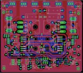
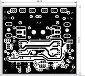
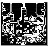
Pictures are postcript output so you can see more how it looks in gerber.
how big are the holes of the connectors?
regards
Attachments
Last edited:
Holes are big - about same as for pins on IRFP240. 1.5 mm dia should work. Don't go any smaller and large pads are great.
Thanks
Thanks
Holes are big - about same as for pins on IRFP240. 1.5 mm dia should work. Don't go any smaller and large pads are great.
Thanks
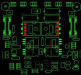
Left polygon is now clean upped.
the space for connectors are big ebough now.
now gerber can be generated, do it tomorrow but give me al the info what you need, type of gerber, drill ets, maybe you have a job file for eagle.
regards
Attachments
I have no idea what is needed. I know that Gerbers generated by Prasi, Sonal, and others seem to have all the right files. I can point you to one and you can look at it to see what is involved.
Here is Gerber for FH9 in zip file. This one is confirmed to be good as I used it to order boards and they worked.
http://www.diyaudio.com/forums/soli...imate-fidelity-amplifier-746.html#post4718422
Here is Gerber for FH9 in zip file. This one is confirmed to be good as I used it to order boards and they worked.
http://www.diyaudio.com/forums/soli...imate-fidelity-amplifier-746.html#post4718422
I have no idea what is needed. I know that Gerbers generated by Prasi, Sonal, and others seem to have all the right files. I can point you to one and you can look at it to see what is involved.
Here is Gerber for FH9 in zip file. This one is confirmed to be good as I used it to order boards and they worked.
http://www.diyaudio.com/forums/soli...imate-fidelity-amplifier-746.html#post4718422
I have download a eagle cam file from a manyfacturer, these is standart and will work, just ask them when need otherwise, she have a cam for eagle most of the time. plotview you can use for check things.
Here is the drill and gerber in a zip. and seem now I am done for the time being with the pcb, it need to build op stage for stage and setup correct idle and voltages, simming is not that perfect. the drivers need to have 25 mA and the Jfets 4 a 5 mA these are indepentend so play with it is the way to go, I go myself make a pcb and start with testing.
Top and bottom copper (.GTL, .GBL)
Top and bottom solder mask (.GTS, .GBS)
Top and bottom silkscreen (.GTO, .GBO)
Drill file, 2.4 leading (.TXT) Tell manufacturer it is 2.4 leading drill file.
regards
Attachments

Last edited:
Thank you, Kees. This is a beautiful layout.
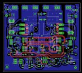
Is there an image that shows the traces (top and bottom different colors) and component silkscreen so that we can double check routing for accuracy? I know you say you use Eagle error checking - but I would still like to be able to follow if visually before sending off to PCB fabrication house.
Thanks,
X
Or is what I am talking about the same as this last image - which is the most current?
- Home
- Amplifiers
- Solid State
- allFET circlotron