@Rod: will try that on sunday ...Try measuring G1 voltage with Ua = 0; then with Ua = 250V using a modern DMM.
@ssr2: can you post a complete scan of your russian ds version, pls
@ both:
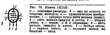
1p24b is actually two pentodes in parallel, except for filaments which can be series or parallel connected.
Now there is a note about 1p22b on radiomuseum that current / power is limited by filament heating due to cathode current:
quote:
1p22b note 2)
The 17mA current is for filaments in Parallel. In Series the IkMax is 10mA. This re-enforces the claim that the limit is not emission saturation but extra heating of the filament due to "Cathode" current.
:unquote
@ssr2: series or parallel filaments ?
I have to check that on sunday, but I believe mine are in series ...
While going through those russian datasheets I discovered a strange inconsistency:
All rod tubes with dual filaments (1j29b, 1p24b, 1p22b) list the CT as "plus" and both outer terminals as "minus" in russian ds.
However, russian schematics and app notes have it the other way round, namely CT at GND and outer terminals "plus".
Don't know whether it matters ...
All rod tubes with dual filaments (1j29b, 1p24b, 1p22b) list the CT as "plus" and both outer terminals as "minus" in russian ds.
However, russian schematics and app notes have it the other way round, namely CT at GND and outer terminals "plus".
Don't know whether it matters ...
Attachments
Sorrento - I know that cathode current significantly contributes to filament heating only in rod tubes with very low filament current, like 1J24B, which has 1,2 V 13 mA filament. 1P24B has 1.2 V 240 mA filament, so extra 16 mA of cathode current should not contribute much to heating. Data sheet says 0.95 to 1.4 V filament voltage is OK.
I use parallel connection of filaments.
Yes, all rod pentodes have two identical sections connected in parallel, but only in 1J37B the two first grids are connected to separate outlet wires.
I think it doesn't matter which filament end is negative and which is positive, as long as the negative end is on the ground side.
Will post full data sheet shortly.
1P24B-V data sheet

Page 1

Page 2

Page 3

Page 4
I noticed in the data sheet that Ug2 should not exceed 200 V and should never, even for a short time, exceed plate voltage. So, from this warning, it would be sensible to connect screen and plate with a resistor whose value is chosen so that Ug2 is about 180-190 V. This should not change triode characteristics significantly.
Also, maximum bulb temperature is 190 C, which is pretty high.
Page 1
Page 2
Page 3
Page 4
I noticed in the data sheet that Ug2 should not exceed 200 V and should never, even for a short time, exceed plate voltage. So, from this warning, it would be sensible to connect screen and plate with a resistor whose value is chosen so that Ug2 is about 180-190 V. This should not change triode characteristics significantly.
Also, maximum bulb temperature is 190 C, which is pretty high.
Just interrupting this interesting exchange about rod tubes to raise the question of SMPS filament supplies into Rod Coleman regs. With my 10Y stage in filament bias my standard filament supply is linear and has a couple of large chokes, 280mH at 2.7A. Works like a charm except that the layout is prone to some hum if it's not optimised and in one incarnation I get some mechanical noise which I'll have to deal with - it's a flimsy aluminium case not an ABS box, which probably filters out the vibration. Output is 24V DC.
So today I tried a Mean Well LRS-50-24. It works, for a start. But the sound isn't as smooth and natural as the linear supply. It's a bit artificial, with a slightly papery quality to vocals. It's not "bad" as such, it's just not the equal of the linear supply and makes the 10Y sound a bit like a digital amp. I've had a suggestion of using a filter between the SMPS and Rod's regs, part of the TUBA stage but without the LM1084. This is new to me and I haven't looked at the circuit. I'm also a valve person and don't have any solid state skills as such. Since I now have the SMPS stage up and working I'd like to see if it could be improved to the point where it competes with a linear supply.
https://www.diyaudio.com/community/...-vfet-theseus-chassis-incl-thump-kill.379747/
So any comments and suggestions? Hopefully Rod will come in here. I was using the V4 regs since I have a few of them and I don't have a V9 at present, since it's with a friend. My goal is the best sound with no hum, of course. This may be easier with the V9 than the V4, with or without my big chokes which, nice as they are, do have a hum field around them that needs dealing with.
Ale shows what Sridhar did on his build in VT-25 Preamps in Lockdown, easiest path for you to follow.
Making a good filter for smps used as filament filament supply needs at least 3 sections, A 100kHz-MHz HF suppression filter involving large ferrites, a hum and noise suppression capacitor multiplier using high bandwith active parts and a regulator (you can use Rod's here).
Making a good filter for smps used as filament filament supply needs at least 3 sections, A 100kHz-MHz HF suppression filter involving large ferrites, a hum and noise suppression capacitor multiplier using high bandwith active parts and a regulator (you can use Rod's here).
Ale shows what Sridhar did on his build in VT-25 Preamps in Lockdown, easiest path for you to follow.
Making a good filter for smps used as filament filament supply needs at least 3 sections, A 100kHz-MHz HF suppression filter involving large ferrites, a hum and noise suppression capacitor multiplier using high bandwith active parts and a regulator e.g. Rod's
Here's Sridhar's circuit. Any comments or suggestions for improvement? Will this ever rival a linear supply?

Thank you for the data.1P24B-V data sheet
I noticed in the data sheet that Ug2 should not exceed 200 V and should never, even for a short time, exceed plate voltage. So, from this warning, it would be sensible to connect screen and plate with a resistor whose value is chosen so that Ug2 is about 180-190 V. This should not change triode characteristics significantly.
Also, maximum bulb temperature is 190 C, which is pretty high.
In the meantime I have done some more experiments to solve the thermal behavior issue I am having.
Disregarding the UG2 max ratings of course ...
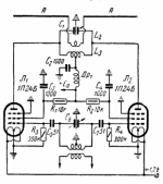
The breadboard setup is like this:
All powersupplies are from a stabilized Lab PS, adjustable.
The setup is as in my application, except that G3 can be tied to either cathode or plate and G1 voltage is applied low impedance to grid, giving grid current no chance to change bias.
1 st case: G3 tied to cathode:
that seems to be the worst case, runaway whenever dissipation exceeds 2.5W.
Unfortunately that is what I did...
2nd case: G3 tied to plate:
Much more stable; I can now carefully and slowly tune bias to some 18mA or 5W and it seems to stay there.
It seems so ... until I turn off plate voltage and let the tube cool down.
After re-applying power to the now cold tube, plate current is down at 11mA ... and stays there ! With a much cooler tube .
Of course I can bring current up again by either more plate voltage or less grid bias and it will again look stable.
Until the next thermal / power cycle.
It seems that tube temperature as a whole has a big influence on tube current.
With G3 tied to plate it now seems to find a stable thermal equilibrium.
But ... this equilibrium depends on temperature ... !
The problem with this is:
If I tune bias to a dissipation of - say - 5W then its fine and pseudo stable at a high bulb temperature.
But on the next cold start dissipation is down to 2.5W and because temperature at lower dissipation stays lower it never returns to the higher.
Unless it is forced to do so by re-biasing ...
Now one might think that's easy to solve: tune bias when tube is cold.
But unfortunately this tube is small and heats up quickly. By the time I am through with tuning its already hot ...😉

Andy, you need -at least- 19V DC (rather 20V) before R.C. V4, so must to use Ohm's law:
24V - Ifilament * (DCR of first choke+series resistors between caps+DCR of CMC)= 19...20V
24V - Ifilament * (DCR of first choke+series resistors between caps+DCR of CMC)= 19...20V
Yes, I know. I really want 24V - that's what I planned for. The V4 regs need 6V headroom, though the V9 needs only around 3.5V. The adjustment on the Mean Well goes up to around 28V. So hopefully should get there somehow. Haven't done the exact calcs yet - depends on the parts. Don't worry - I use Ohms law and many other calcs all the time, I have all the calcs in a huge Excel spreadsheet which I'm always adding to. I'm a psychologist so I'm used to spreadsheets and calculations.Andy, you need -at least- 19V DC (rather 20V) before R.C. V4, so must to use Ohm's law:
24V - Ifilament * (DCR of first choke+series resistors between caps+DCR of CMC)= 19...20V
Thanks for sharing your experience. I am still puzzled with the power discrepancy between different data sheets. I have seen original Russian data sheets with 2.5 W plate and 1 W screen limiting dissipation. What to believe?Thank you for the data.
In the meantime I have done some more experiments to solve the thermal behavior issue I am having.
Disregarding the UG2 max ratings of course ...
The breadboard setup is like this:
View attachment 1116684
All powersupplies are from a stabilized Lab PS, adjustable.
The setup is as in my application, except that G3 can be tied to either cathode or plate and G1 voltage is applied low impedance to grid, giving grid current no chance to change bias.
1 st case: G3 tied to cathode:
that seems to be the worst case, runaway whenever dissipation exceeds 2.5W.
Unfortunately that is what I did...
2nd case: G3 tied to plate:
Much more stable; I can now carefully and slowly tune bias to some 18mA or 5W and it seems to stay there.
It seems so ... until I turn off plate voltage and let the tube cool down.
After re-applying power to the now cold tube, plate current is down at 11mA ... and stays there ! With a much cooler tube .
Of course I can bring current up again by either more plate voltage or less grid bias and it will again look stable.
Until the next thermal / power cycle.
It seems that tube temperature as a whole has a big influence on tube current.
With G3 tied to plate it now seems to find a stable thermal equilibrium.
But ... this equilibrium depends on temperature ... !
The problem with this is:
If I tune bias to a dissipation of - say - 5W then its fine and pseudo stable at a high bulb temperature.
But on the next cold start dissipation is down to 2.5W and because temperature at lower dissipation stays lower it never returns to the higher.
Unless it is forced to do so by re-biasing ...
Now one might think that's easy to solve: tune bias when tube is cold.
But unfortunately this tube is small and heats up quickly. By the time I am through with tuning its already hot ...😉
One possibility is that there was an up-rated version of 1P24B. The data sheet that I posted came with a factory-packed batch of 50 tubes. I only used tubes from this batch.
One thing sure is that 5 W power may be too optimistic for a generic 1P24B - in the absence of data sheet for a specific batch.
Why using SMPS if you can make a perfect (or almost perfect) linear supply?Just interrupting this interesting exchange about rod tubes to raise the question of SMPS filament supplies into Rod Coleman regs. With my 10Y stage in filament bias my standard filament supply is linear and has a couple of large chokes, 280mH at 2.7A. Works like a charm except that the layout is prone to some hum if it's not optimised and in one incarnation I get some mechanical noise which I'll have to deal with - it's a flimsy aluminium case not an ABS box, which probably filters out the vibration. Output is 24V DC.
So today I tried a Mean Well LRS-50-24. It works, for a start. But the sound isn't as smooth and natural as the linear supply. It's a bit artificial, with a slightly papery quality to vocals. It's not "bad" as such, it's just not the equal of the linear supply and makes the 10Y sound a bit like a digital amp. I've had a suggestion of using a filter between the SMPS and Rod's regs, part of the TUBA stage but without the LM1084. This is new to me and I haven't looked at the circuit. I'm also a valve person and don't have any solid state skills as such. Since I now have the SMPS stage up and working I'd like to see if it could be improved to the point where it competes with a linear supply.
https://www.diyaudio.com/community/...-vfet-theseus-chassis-incl-thump-kill.379747/
So any comments and suggestions? Hopefully Rod will come in here. I was using the V4 regs since I have a few of them and I don't have a V9 at present, since it's with a friend. My goal is the best sound with no hum, of course. This may be easier with the V9 than the V4, with or without my big chokes which, nice as they are, do have a hum field around them that needs dealing with.
SMPS use capacitor input filter in front of the oscillator. In addition to RF noise, they also produce broadband audio rectification noise. From the engineering point, it is better not to make noise, in the first place, than trying to suppress it. Noise suppression is a non-trivial task.
My favorite approach to DC filament is center-tap transformer secondary, two slow-switching diodes with as low forward voltage as possible, choke input filter with large smoothing capacitors, and CM+DM chokes between filter and filament. No regulators.
I have seen original Russian data sheets with 2.5 W plate and 1 W screen limiting dissipation. What to believe?
Your ds is for the -dash-v ... the 1st I've seen, maybe that makes the difference ?
The common ones all have the lower rating as attached.
I just re- wired my PTTPSEARDHT (Proto-Type-Triple-Parallel-Single-Ended-All-Direct-Heater-Tube) amp (aka SixPack) with G3 tied to plate and bias increased to 4W dissipation; post #44;
one of the 6 tubes is rock stable, one is still going up and down more than I like, the rest is somewhere in between, but no serious excursions any more.
Envelope temp is now at 100 C / 212 F by the way ...
Attachments
Last edited:
I also use choke input filter + choke between positive supply and DHT filament. But only DM chokes. Any CM choke recommendation for tubes such as 01a? Thanks!Why using SMPS if you can make a perfect (or almost perfect) linear supply?
SMPS use capacitor input filter in front of the oscillator. In addition to RF noise, they also produce broadband audio rectification noise. From the engineering point, it is better not to make noise, in the first place, than trying to suppress it. Noise suppression is a non-trivial task.
My favorite approach to DC filament is center-tap transformer secondary, two slow-switching diodes with as low forward voltage as possible, choke input filter with large smoothing capacitors, and CM+DM chokes between filter and filament. No regulators.
CM choke is very simple to make. It is bifilar wound, with wire of appropriate thickness for the current, on any gapless core, EI alternate stack, or (preferably) toroid. Forward and return wires to filament are connected in a way that DC runs opposite directions through winding halves, thus cancelling DC magnetization. I particularly like o-cores (round cross-section) from AlphaCore, which is now part of Goertz Audio. Low prices, and they do small orders.I also use choke input filter + choke between positive supply and DHT filament. But only DM chokes. Any CM choke recommendation for tubes such as 01a? Thanks!
Last edited:
Same here - large DM choke for my 10Y stage in filament bias, 128mH, 2.7A, plus 10,000uF capacitor. So is the right place for the CM choke after the cap?I also use choke input filter + choke between positive supply and DHT filament. But only DM chokes. Any CM choke recommendation for tubes such as 01a? Thanks!
What value CM choke? I have some Epcos 18mH, 2A. Is that in the ballpark for a 10Y or what do you suggest? Is the CM choke followed by a cap or does it go straight into the filaments or straight into Rod's reg?
As sser has suggested, you must ask yourself why you need to use a mains→DC unit at all. It will always require careful selection of the unit, and it is still difficult to be sure that the one you choose can be made usable. Then you will need to apply many kinds of precautions and remediations to contain the large amount of wideband conducted AND radiated noise.So today I tried a Mean Well LRS-50-24. It works, for a start. But the sound isn't as smooth and natural as the linear supply. It's a bit artificial, with a slightly papery quality to vocals. It's not "bad" as such, it's just not the equal of the linear supply and makes the 10Y sound a bit like a digital amp.
And even after a lot of effort, the 50/60Hz transformer solution may still be better.
I know that many constructors believe that since these units seem to work OK for some transistor power amp systems, that all you need is a little light filtering, and they are ready for any purpose, including DHT heating supplies. But there is one critical difference: DHT heater supplies require the Raw DC to be floating. Any leakage current will run through (part of) the filament; and if cathode bias or filament bias is adopted, through the cathode resistor/bypass capacitor a well. BUT with Line→DC converters, the leakage current is a wideband noise current; and means: wideband noise current is mixed directly with the audio signal current.
This is a conflict for the operation of a Line→DC PSU, because they rely on having the input and/or the output AC (and/or DC) coupled to PE (protective earth). If this PE connexion is lifted, or we add a series impedance to it (especially inductive), then we are wrecking its EMC performance. Recent converters make it difficult to lift the AC coupling, since the capacitors are built into the unit; the caps typically shunt input and output to the PE terminal of the mains connector. If you look at your amp's schematic you'll see that the output→PE cap is in parallel to your amp's cathode/filament bias resistor: IOW you get an unwanted cathode bypass cap, made of some unpleasant dielectric, connected to PE. OK, if you use grid bias, this path is a low impedance path - but it still connects to the same PE point that is shared with the converter's input filter cap (and this filters the dirtiest node in the converter).
I made some other remarks on the subject here:
Comments on Line→DC units for DHT filament heating
If you are still not put off by any of this - my recommendations for mitigating the effects of the noise.
- Connect amp chassis to PE as normal, but add 10Ω wirewound resistor from signal 0V to chassis
- No other paths from DAC or MC 0V to PE.
- DAC and MC stages in shielded enclosures; maybe with VHF filtering added to the outputs (care and understanding required)
- Use grid bias. Otherwise, any leakage current will flow though the cathode R || C.
Filtering: the objective is to DIVERT the noise: not to block it from its necessary return-path.
- Use a common-mode choke in the Raw DC lines; 1-10mH, mounted near to the converter end of the cable. connect caps (470nF 630V stacked-construction MKP) from + and - to PE.
- add a LOW VALUE choke 22-100µH in series with the + Raw DC input, and a cap (1 - 5µF stacked MKP, or DC-LINK) to Raw DC -ve. The RC regulator will deal with any audio frequency differential mode noise. Large-value inductors at the input may raise the impedance in the ultrasonic or audio range, which does not help.
- Plug the converter into its own wall socket (the PE of this cable carries EMC ground current).
- Keep the converter as far as possible from any DAC, MC cartridge, MC head amp, any module with opamps designed before year 1997 (the value of EMC hardening of opamps was recognised around then). DACs are very susceptible to radiated emissions, or any risk that the ground noise current can leak back through the DAC outputs. Any noise at the DAC's oscillator power supply can render phase noise into the oscillator, that will degrade the sound notably.
I admit it is not easy, but Rod, Andy wants to use filament bias, one terminal of the supply will be connected to ground - not floating anymore.... DHT heater supplies require the Raw DC to be floating...
Filament bias is better. But what is the impedance of the ground loop?Andy wants to use filament bias, one terminal of the supply will be connected to ground - not floating
Connecting the output to 0V, and then to PE is creating a long loop carrying the leakage current, and the effective return-path does not have zero impedance through the bandwidth the noise; the risk of ground-loops at high frequencies (which measure quite strongly up to 300MHz or more) remains to be solved. The same filtering, and all the other precautions need to be attended to, in order to divert and shield against as much of the noise as possible.
- Home
- Amplifiers
- Tubes / Valves
- All-DHT amplifiers: no indirectly heated signal tubes!