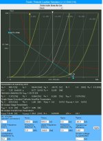
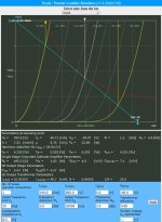
Looks like that toob would smoke a Kat! 😱really cool looking tube
Thanks for the excellent response. My normal loud, room filling listening is about 1/4watt(with helper subs).The point I was trying to make is that squeezing the maximum power output from a particular tube doesn't offer much in terms of practical listening benefits. It might be satisfying from a technical design standpoint but in terms of increased volume and headroom the difference between 85% and 100%, for example, is minimal and in many cases imperceptible.
It takes 10x the wattage to make something sound "twice as loud" subjectively. So if your amp is running at 85% (just a random example) and you need more volume / headroom you'd get better results by using an amp / tube that provides significantly more power than by trying to squeeze all the power you can from your existing amp. Or by using more efficient speakers.
As for your question, I'm not real good with math but I'll take a shot at it. I'm sure others can provide the exact formula.
Every time you double the power (x2, a 100% increase) you get an extra 3db when measured at 1m. So, conversely, every time you cut the power in half (x0.5, a 50% decrease) you get a 3db decrease when measured at 1m.
So if 1w produces 100db then .5w will produce 97db . . . and .25w will produce 94db . . . and .125w will produce 91db . . . so 0.0625w will produce 88db . . . then 0.03125w will produce 85db.
So, if you listen at a distance of 1m from your 100db speaker it looks like you'd be using just over 0.03w to produce 85db. If you sit further away from your speaker it would require more power to produce the same 85db.
Other factors also come into play such as room acoustics and the fact that most people are listening to a pair of speakers unless you run a mono system. Seating position, whether on axis or off axis, would be another. So I'm sure this is an oversimplification.
I suppose the amount of headroom would depend on how much power your amp has. A 2w amp will have less headroom than a 30w amp if both are used under the same conditions.
But the importance of headroom varies significantly depending on the recording.
Some types of music tend to be recorded with significantly more dynamic range than others. More of a difference between the quietest and the loudest portions of the recording. Classical music recordings tend to be considerably more dynamic than more popular types.
Some genres tend to be recorded with a significant amount of compression in an effort to make the recording sound louder. The average volume level can be increased because the dynamic range has been reduced during the recording and mastering process.
Also, tube amps tend to clip "softer / more gracefully" than SS so in the event that you run out of headroom it might not be as noticeable or bothersome.
I’ve been listening to 3 stage all DHT for 6 years. Transparency and detail with a deep wide sound stage in the midrange.
Anyone got a schematic for a 2-stage px25 amp and dht driver? I’ve always wanted to try such an amp out.
Just drive the PX25 with another PX25 and a 1:2 step up transformer on the input. I have thought about building a px25 amp like that for a long time.
Hmm..what would the source need to be capable of swinging to drive a PX25 at input via a 1:2 SUT, and for full output power?
Around 2v if you use a decent CCS to load the first tube. If you look at the data sheet you will see that the maximum recommended bias setting is at 400v and -31v on the grid. So to we know we are going to need to swing twice the bias voltage in order to drive the tube to max output or 62v peak to peak.
We also know that the px25 has a gain of 9.5 and you can get reasonably close to that figure if you load the peamp px25 with a ccs. But lets say that you are using a used nos tube and it can only get a gain of 8. So if we divide 62 by 8 we would need an input voltage of 7.75 peak to peak. Divide this number by half to account for a 1:2 step up transformer and we get 3.875v peak to peak. If you convert this number to RMS, the input voltage needs to be about 1.37v rms.
So I figure if you have a standard 2v rms dac output, it should be able to drive the amp with a little bit of headroom to spare.
The only real gotcha is that your dac has to have a reasonably low output impedance so that you don't roll off your highs. Preferably the output impedance should be 2K or less.
Sweet. Thank you. So, good 1:2 SUT and CCS load... Nice. Could it be done with an Interstage also (no coupling cap)?
You can, the problem is that the transformer is not going to get quite as much gain as a CCS would, so you might want to bump it up to a 1:2.5 or 1:3 ratio to be on the safe side. It is also worth pointing out that while you no longer have a coupling cap in your signal path, you have actually replaced it with your power supply capacitor.
What would be better would be to use a parafeed interstage. You will still have a coupling capacitor, but now you can use the capacitor in combination with the plate choke to actually maintain low frequency response instead of rolling it off with a normal coupling cap.
What would be better would be to use a parafeed interstage. You will still have a coupling capacitor, but now you can use the capacitor in combination with the plate choke to actually maintain low frequency response instead of rolling it off with a normal coupling cap.
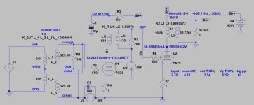
@daanve: from a simulation point of view, this is irrelevant. If that bothers anyone, change the secondary outputs.
This schematic origin was a pure transformer loaded preamplifier, where input signal and output signal was "in phase". I reused it to model this amplifier.
BTW if you want to make -in reality- "phase correct" tube amplifier, usually one phase switching needed. The most critical is the OPT, so it must be done in previous stages.
When using dots to indicate transformer phase, draw correctly, or don't use dots.
You specify Sowter input transformer and Monolit Magnetics output transformer, but I don't see which IT is suggested.
It depends on the IT properties. With a 1:1 bifilar wound IT you must connect phases correctly.
In a two stage SE amplifier, input/driver tube and output tube switch phase. When phase correct transformers are used, no switching is needed to get "absolute phase correct" signal at output.
Anyone got a schematic for a 2-stage px25 amp and dht driver? I’ve always wanted to try such an amp out.
I only have 3 schematics for that tube, this is the closest:
I'm not posting on forums much lately and I had forgotten about this thread . . . but here's a link to the all DHT amp that I recently built. It's also directly coupled and incorporates the Hammond SUTs that Andy is using.
https://www.audiokarma.org/forums/i...ckeyed-monkey-a-directly-coupled-set.1040847/
https://www.audiokarma.org/forums/i...ckeyed-monkey-a-directly-coupled-set.1040847/
It's one of my Slagle 1:1 IT, but it's indifferent. Any 1:1 appropriate IT usable... but I don't see which IT is suggested.
Jumping into this old thread, that is about what I want to achieve. As it is a low budget build, no chokes or IT´s are possible.
Having read a lot about 4P1L having a nice price, it will surely work for the front end. As I have a good stock of 6B4G, I can use it both as driver and output. Have to decide on the heater regulators though. The simmed .four indicates acceptable figures at 1W. This is the sketch:
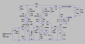
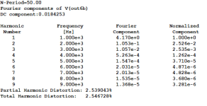
Having read a lot about 4P1L having a nice price, it will surely work for the front end. As I have a good stock of 6B4G, I can use it both as driver and output. Have to decide on the heater regulators though. The simmed .four indicates acceptable figures at 1W. This is the sketch:


Attachments
Last edited:
- Home
- Amplifiers
- Tubes / Valves
- All-DHT amplifiers: no indirectly heated signal tubes!
