Ok, at the risk of blowing myself to smitherines, i have been planning a high power aleph x for a while. BUT, my requirements are decent power ...100-200wpc into 8 ohms and also that at least into 2 ohms. So how do we accomplish this without a crazy bias setting ...like 30A. According to the simulator, 22vdc at 10A bias gives 100 wpc into 8, 200 into 4, and 100 into 2. Sounds good to me, but I want more flexibility. At the expense of a lot of time consuming work and $$, is it possible to, supposing I have a custom toroidal wound to multiple voltages all above 1kva, plenty of heatsinking, and lots of relays. Is it possible to have a switch that switches between say 17v, 22v, 32v taps and corresponding pots that control individual bias settings AND dc offset for all 3 voltages. This way, the switch optimizes voltage and bias and dc offset for 3 different impedence loads, 8, 4, 2 ohms, but keeps output at those 3 different loads at about 200 wpc. Yes, I know if you simulate this i need 24 output devices, and probably 1.5kva toroids and 600 watts per channel of heat dissipation....no problem :-D Would this be too much work? not worth it?
OR, is there another option such as just shutting down some transistors...again via relays or whatever...that'll decrease the current draw and bias....so I can set current and bias super high for "high power" mode and run the amp at like 700 watts dissipation (per channel) but if I don't want to run it like that all the time, I can switch from say 24 output devices down to 12 or even say 6 devices. ? Good idea bad idea?
i have a friend that has an aleph x that he built, and he is also working on higher power aleph x's, so he'll be able to help me out some...so I don't blow myself up...so don't worry about me too much 🙂 thanks guys!
-Matthew K. Olson
Well, I don't have the $$ now, nor the time, but both are coming, so I'd love to know if this is a good idea or a bad idea. 🙂
i have plenty of heatsinks...and yes the monoblocks will weigh about 150lbs each if this whole idea works! haha!
-Matthew K. Olson
i have plenty of heatsinks...and yes the monoblocks will weigh about 150lbs each if this whole idea works! haha!
-Matthew K. Olson
Referring to http://www.diyaudio.com/forums/showthread.php?postid=275333#post275333 (I though it was better to post it here, hope you don't mind yldouright), I attached a picture with equal calculation inputs.
I didn't do the math but to me it seems unlikely that one can get more than 300W/3ohm out of a supply of +/-25V @ 6.8A.
With 25V/12A the max power would be 529W into 2ohm
/Hugo 🙂
I didn't do the math but to me it seems unlikely that one can get more than 300W/3ohm out of a supply of +/-25V @ 6.8A.
With 25V/12A the max power would be 529W into 2ohm
/Hugo 🙂
Attachments
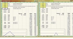
Just so that no one gets confused, the numbers posted by Netlist in the left spreadsheet reflect the correct calculation. I've checked the spreadsheet and there are multiple errors for the calculations on the right.
1) It doesn't consider that the supply is +/-V, so power dissipation is a factor of 2 low.
2) The bias current is split between the two halves of the circuit, so the peak current is also off by a factor of two.
Jeremy
1) It doesn't consider that the supply is +/-V, so power dissipation is a factor of 2 low.
2) The bias current is split between the two halves of the circuit, so the peak current is also off by a factor of two.
Jeremy
Maybe a very odd question! But the 1.1, 1.2 and 1.3 in the sheet! Are these factors of multipli the rail voltage due to using a filter CLCLC or CRCRC?
Than it makes sense for me.
Nils
Than it makes sense for me.
Nils
Well, I guess no one is confused. It's not a bad idea to have different opinions from time to time.yldouright said:Here it is. Sorry Ted
You probably made a mistake but did you're homework well. 😉
If Wuffwaff's calculation were wrong someone would have told us long ago.
I guess it's the regulation factor of the transformer.But the 1.1, 1.2 and 1.3 in the sheet!
From PSU Designer:
Correct me if i'm wrong.Regulation %
The regulation of the transformer as specified by the manufacturer. Describes the ratio between on-load and off-load voltages, and is expressed in percent.
Typical values range from 5% to 25%.
/Hugo 🙂
mmmm,
well the first version was allright. I´m not responsible for all the later versions of berekening but if I remember right the v2 and 3 were basically the same with some usefull extensions.
Another thing I see in the one on the right hand side is the dissipation wich is only half (170 watts instead of 340 watts, 6,8Ax50V x 2)
william
 Look what they done to my song, ma
grataku said:another year, another AX bulk purchase...
A properly dimensioned 50W/chn stereo version will weight in the neighbor of 35kg dissipate 275W with the chassis at 50 deg C.
 It's way too late to dig up the formulas now, and I have
 never dealt with heat dissipation calculations before, so can someone help understand what it would mean to have 6 channels at 30 to 40 watts each - heat wise. From the figure above, it would be around 1KWatt of heat. It sounds huge, but what does it really mean? What will it do to my room temperature? I am set on going 3-way amped, and the heat will be the deciding factor, since I am in Texas, and it already costs USD 150 per month to cool a condo in summer. Excuse the smilies, but I am trying to convey how it feels here in summer.
Coulomb said:Grataku, where would one find these PCB's for a 200 Watt Aelph X?
🙂
Anthony
Anthony,Coulomb said:How might one get such boards? 🙂
Anthony
See here where Edwin Dorre made a 130wpc AX with 16 output devices per channel. As you can see, he used P-t-P to wire the 4 banks of 4 devices.
http://passdiy.com/gallery/alephx-p3.htm
200wpc will need 4 banks of 6 devices (depending on the per device power disipation). You could use Dale's (Harvardian) output boards, if there are any around.
http://www.diyaudio.com/forums/showthread.php?postid=64019#post64019
It would be like having one of these in your listening room.amo said:
http://www.heater-home.com/heaters/electric-qmark-3ug62.html
Without the fan.
Knowing that hot air rises, you could duct the heat to the outside.
amo,
six channels 0f 40 watts will give around 6x40x2.5= 600 watts of heat. The faktor 2.5 stands for around 40% efficiency wich is probably a bit too high.
william


six channels 0f 40 watts will give around 6x40x2.5= 600 watts of heat. The faktor 2.5 stands for around 40% efficiency wich is probably a bit too high.
william
Roddyama I have 24 of Dales output boards and still have 10 of the FEB as well, yes I have built 2 Aelphs with them so far. So with Chad's boards I would parallel Dales boards off of the outputs?
Anthony
Anthony
- Status
- Not open for further replies.
- Home
- Amplifiers
- Pass Labs
- Aleph-X: High-Power Version