Macka,
Putting up with WAF would be no problem if i were as lucky as
you are mate!
keep us posted on your X conversion, and keep her happy while
you're at it... and get a better camera! 😉
m.
Putting up with WAF would be no problem if i were as lucky as
you are mate!
keep us posted on your X conversion, and keep her happy while
you're at it... and get a better camera! 😉
m.
Taco,Taco said:Good work Macka you're working fast 🙂. But do you need the extra power of the larger X? You have very sensitive speakers I thought.
/Taco
I agree on the good work part, but IMHO, there is no such thing as too much power
 , only too much noise
Why thankyou chaps,
I will try an keep you all abreast of the more interesting aspects of the project!!
Sorry, but I am late for todays diy audio tutorial.
According to my notes todays class is all about heat transfer and the importance mica washers.
With class A heatsinks are first and foremost.
macka
I will try an keep you all abreast of the more interesting aspects of the project!!
Sorry, but I am late for todays diy audio tutorial.
According to my notes todays class is all about heat transfer and the importance mica washers.
With class A heatsinks are first and foremost.
macka
Attachments

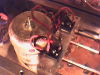
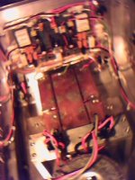
A more detailed view showing the 2 bridge recifiers on the aluminium bridge of the filter capacitors.
This eased the layout of the original amp and makes for a handy heatsink.
I understand dual bridge rectifiers does a better job, but I used 2 for sharing the work load as twice the current flows with the X Aleph, and it would eleviate any mis match between the transformers.
This was actually quite a difficult job, tryng to loom those 14 gauge secondaries and getting a nice clean shiny solder joint with a big %$#@ hot Iron is not easy.
macka 😎
Attachments
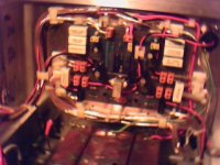
The main wiring from the boards will be next....another night.
I am still not sure about the orientation of the driver board yet.
I used stick on board stand offs get an idea of the cable looming.
The problem is its a bit cramped this way, but it avoids wires crossing the board too often. I'm not sure if this really matters much but its nice to make it neat job if you can.
If I was building it from the ground up I would have the complimentry output fets on either side, but this is of course not the case with the normal Aleph where you match the CCS and active side seperately.
macka🙂
Attachments

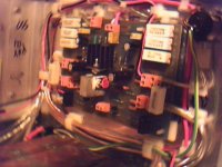
I have started the wiring up.
I had to decide on whether to keep the 2 way screw termnals on the board and provide strain relief with clamps or remove them and solder directly to the board.
Well, for at least the time being I will continue with the terminals.
As you can see (I hope) with so many wires and the weight of the wiring on the 2 way screw terminals I made liberal use of adhesive cable clamps to the rear panel.
Don't worry it looks better in the flesh (some real pics in a few days)
macka😎
Attachments

One more go.
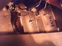
The thick gold snake along the bottom of the board is a double cable run to the Speakon output connector. There was provision for two wires from each 2 way terminal block so what the hell.
I figure it was the only area where there was is " high transient signal current" to the outside world and the way this thing delivers it might help.
No whimpy 2 watt full range drivers on the end of this Baby though, she would blast them into orbit.
macka😎
Attachments
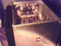
Good news,
I have 1 channel of X Aleph 100 up, It goes and is warming up as I write this post.
The bias is set for 6.30 amps, offset is 18 mv and absolute offset after warm up is 20mv (tweekable to nil).
The rails are 25-26 volts depending on the AC mains supply....
Thankyou to Mr Pass and the Passlabs crew for allowing us to re create Pass designs in diy format and everyone on the forum for their ideas & assistance.
macka
🙂
Attachments
Some real pictures soon......
If you have any questions or comments please fire away.
I only posted this series to illustrate that you can convert Aleph to X Aleph if you really try.
After hearing the baby X, I figured it was the only realistic option for me given funds, space and precious time.
macka🙂
If you have any questions or comments please fire away.
I only posted this series to illustrate that you can convert Aleph to X Aleph if you really try.
After hearing the baby X, I figured it was the only realistic option for me given funds, space and precious time.
macka🙂
Attachments
Good question.
I accept PayPal, just email me for my email address.
Okay, I use the web cam for the odd pic here and there.
I find my regular Nikon pics when run via the scanner beside me are better than any Digital camera I can afford....alas the convenience of digital.
macka
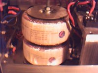
Ps Just connected speaker....absolutely no noise or hum..yippy.
So those toriodal chokes really do work
I accept PayPal, just email me for my email address.
Okay, I use the web cam for the odd pic here and there.
I find my regular Nikon pics when run via the scanner beside me are better than any Digital camera I can afford....alas the convenience of digital.
macka
Ps Just connected speaker....absolutely no noise or hum..yippy.
So those toriodal chokes really do work
Since its been going..about an hour now, I've come to appreciate the additional losses in terms of heat with the X Aleph, that is the higher current draw does cause voltage losses which must be accounted for in your box design for heat losses (ie AX 200 specs)
The bridge rectifiers which are mounted on a solid length of aluminum bar are quite hot, the chokes are hot and the dual transformers (300+300VA) are now quite warm....thats with the lid off.....
 .
.
One may have to investigate some additional ventilation the box!
macka
The bridge rectifiers which are mounted on a solid length of aluminum bar are quite hot, the chokes are hot and the dual transformers (300+300VA) are now quite warm....thats with the lid off.....
.One may have to investigate some additional ventilation the box!
macka
Hi guys, I noticed many of you like me built the aleph 2 & now want to convert to the X. I myself have purchased the aleph X boards too. The only major change must be the transformer. So I thought maybe the existing aleph 2 can be X-ed by just soldering on a few components?? What I mean is getting some of the benefits of the X sound in the front end but retaining the single ended output of the aleph2s. This way all voltages can remain, saving money on transformers, capacitors etc. Does it work that way?? Or must we really construct the full balanced for the circuit to actually work? Pardon the dumb questions, but it came about because of refusal to spend too much money and using the old trannies as door stoppers(I'm a student u see)......
macka said:Since its been going..about an hour now, I've come to appreciate the additional losses in terms of heat with the X Aleph, that is the higher current draw does cause voltage losses which must be accounted for in your box design for heat losses (ie AX 200 specs)
The bridge rectifiers which are mounted on a solid length of aluminum bar are quite hot, the chokes are hot and the dual transformers (300+300VA) are now quite warm....thats with the lid off.....
One may have to investigate some additional ventilation the box!
macka
That's what I just realized making my discrete bridges: first I tried some Fairchild Stealth 30A-600V, but then I was forced to switch to Shottkys (voltage drop is about the half...which is good with my small bridge heatsinks..)
The Stealth will be used for other purposes....
Cheers
Andrea
Kenny,
For the best explanation see the first few pages of the X Alpeh thread by Grey Rollins. In a nut shell..no can do.
The only way you could use the existing supply is if you made an Series Pass amp, but it would be seriously too powerful and unmanagable by all...and still only biased to 100 watts but worth a thought. Do a search for Uli 's design and layout? if you are interested.
macka
Thanks Macka, so no ultra-high power aleph X for now......
To all:
As I may have mentioned before my transformer has 2*35vac windings which may be paralleled. This would give ~45vdc single supply which may be just right for a 100w alephX. Read on......
I have got back to look at the aleph X schematic again. The original alephs is single ended so there is no escaping the split supply needed. But since the X amps are bridged, does that still require the centre-tap? Maybe just a simple virtual ground to reference the low current input stage??
I did a quick search and found this: http://www.diyaudio.com/forums/show...ight=crown macrotech transformer&pagenumber=2
though I do not understand a word of it
Maybe someone can show us the light Please help us save throwing out the old transformers!
To all:
As I may have mentioned before my transformer has 2*35vac windings which may be paralleled. This would give ~45vdc single supply which may be just right for a 100w alephX. Read on......
I have got back to look at the aleph X schematic again. The original alephs is single ended so there is no escaping the split supply needed. But since the X amps are bridged, does that still require the centre-tap? Maybe just a simple virtual ground to reference the low current input stage??
I did a quick search and found this: http://www.diyaudio.com/forums/show...ight=crown macrotech transformer&pagenumber=2
though I do not understand a word of it
Maybe someone can show us the light
Please help us save throwing out the old transformers!- Status
- Not open for further replies.
- Home
- Amplifiers
- Pass Labs
- Aleph-X: High-Power Version