I didnt understand your setting AC gain description(its possible because english is not my native)i did it another way- feeded speakers with 60hz tone, disconected R12/34, then measured AC voltage between source resistors of gain fets, writed value , then without power off soldered some values until achived half of them voltage. in my case r12/34 value was 1538ohms. greys 12k means that more current are by CCS.
fro the past i have tried to get more current from CCS (my always big head pain is 2-4ohm speakers I need to work) but didnt get much better bass just sond become leaner. I also tried to lower voltage railsbut amp start clipping very early(I belive voltage limited clipping) for small and(reasonably) heat friendly amp i found 18v rails and 8A bias per channel and 50% current by CCS is optimal in real world conditions.
fro the past i have tried to get more current from CCS (my always big head pain is 2-4ohm speakers I need to work) but didnt get much better bass just sond become leaner. I also tried to lower voltage railsbut amp start clipping very early(I belive voltage limited clipping) for small and(reasonably) heat friendly amp i found 18v rails and 8A bias per channel and 50% current by CCS is optimal in real world conditions.

Hi!
I wan't to build low version of AlephX (40W/8R) and I to plan build monoblock's (300va transformers per channel), but i can't decided which wersion buy;
2x12V or 2x13V AC
PSU: 44mF + 0R1 + 44mF, double bridge
😕
Thank's for help
Regards
I wan't to build low version of AlephX (40W/8R) and I to plan build monoblock's (300va transformers per channel), but i can't decided which wersion buy;
2x12V or 2x13V AC
PSU: 44mF + 0R1 + 44mF, double bridge
😕
Thank's for help
Regards
Seeking Aleph-X PCBs
I know I can get a set from http://www.kk-pcb.com/.
I was wondering if anyone had a pair that matches the group buy for sale.
I know I can get a set from http://www.kk-pcb.com/.
I was wondering if anyone had a pair that matches the group buy for sale.
Pass DIY Addict
Joined 2000
Paid Member
Up and running (for a short while...)
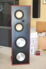
Between work, work, and work, I've had some time to get two 100w Aleph-X amps up and running and finish construction on a pair of dipole speakers and have a listen! What glorious sound - my conventional "box" speakers just don't seem to sound right anymore 😀
Anyhow, the amps ran great and sounded great (especially with the new speakers - bottom drivers are twin 12" and the mids are twin 8" so they play very cleanly to very high levels). At the end of my listening session, I let the speakers run with some white noise for about 24 hours. The next day, both of my amps failed within a few minutes of turning them on. The loud groan from the transformers led me to investigate the power supply configuration and I discovered that the bridge rectifiers (sourced as surplus, rated to 600v and 35a) in both amps had failed and were shorting the transformer which caused the fuse to blow. Apparently, over the course of 24 hours, the heat and current was too much for them.
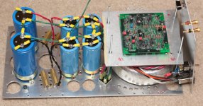
The 1500va transformer has dual secondaries, each rated at 20v. One secondary powers the positive rail, the other powers the negative rail, so each bridge is running at 21v and 9a. The other bridge is mounted in a symmetric manner to the first one that is visible in the picture below. I thought having them mounted to the bottom of the chassis was enough, but when I removed them, I noticed I didn't have a silpad under them like I thought I did. So I've replaced them with another 600v 35a that can handle 35a at 50c and even at 75c can still pass 25a. This time, I'll remember the sil-pad for heat transfer...
Between work, work, and work, I've had some time to get two 100w Aleph-X amps up and running and finish construction on a pair of dipole speakers and have a listen! What glorious sound - my conventional "box" speakers just don't seem to sound right anymore 😀
Anyhow, the amps ran great and sounded great (especially with the new speakers - bottom drivers are twin 12" and the mids are twin 8" so they play very cleanly to very high levels). At the end of my listening session, I let the speakers run with some white noise for about 24 hours. The next day, both of my amps failed within a few minutes of turning them on. The loud groan from the transformers led me to investigate the power supply configuration and I discovered that the bridge rectifiers (sourced as surplus, rated to 600v and 35a) in both amps had failed and were shorting the transformer which caused the fuse to blow. Apparently, over the course of 24 hours, the heat and current was too much for them.
The 1500va transformer has dual secondaries, each rated at 20v. One secondary powers the positive rail, the other powers the negative rail, so each bridge is running at 21v and 9a. The other bridge is mounted in a symmetric manner to the first one that is visible in the picture below. I thought having them mounted to the bottom of the chassis was enough, but when I removed them, I noticed I didn't have a silpad under them like I thought I did. So I've replaced them with another 600v 35a that can handle 35a at 50c and even at 75c can still pass 25a. This time, I'll remember the sil-pad for heat transfer...
Attachments
A silpad will isolate your bridge case from ground...your fuses will not blow and protect your amp next time this happens. Just use thinly spread goop for thermal transfer...
Pass DIY Addict
Joined 2000
Paid Member
Hmmm - I thought perhaps the diodes blew and ended up shorting the secondary leads from the transformer with ONE ANOTHER. I didn't consider that the diodes were shorting to GROUND through the case... Looks like I should do some measuring of the dead rectifiers!
Thanks for the warning, Blues!
Thanks for the warning, Blues!
Pass DIY Addict
Joined 2000
Paid Member
Well, good thing is it could have been worse 😉
YIKES! I'm beginning to realize this... I suppose driving AC into the caps and eventually the FETs would not be pretty. The only part of the amp that is fuse is "hot" side of the transformer primary. Does anyone use fuses anywhere else?
Hmmm - I thought perhaps the diodes blew and ended up shorting the secondary leads from the transformer with ONE ANOTHER. I didn't consider that the diodes were shorting to GROUND through the case... Looks like I should do some measuring of the dead rectifiers!
Thanks for the warning, Blues!
That could be too...but it is still wise to have the bridge case grounded.
Pass DIY Addict
Joined 2000
Paid Member
A quick look around reveals lots of electrically insulative thermal grease (arctic silver, etc). Where can I find the electrically conductive stuff?
Pass DIY Addict
Joined 2000
Paid Member
I came across a curious behavior while I was playing around with my fried rectifiers. One of my amps is built with a 750VA transformer with two 18vac secondaries and a 600v 35a bridge rectifier for each secondary that feeds a cap bank totaling 290,000uF per rail. I'm pulling about 9A out of each rail. This particular transformer buzzed quite loudly in this configuration (which I why I'm rebuilding using 1500va transformers).
The interesting part is that I was experimenting with various power supply configurations since the rectifiers died and it made the transformer VERY quiet. The configuration that made the difference is to have the transformer connected to rectifiers as usual, but from the rectifier rather than having a straight bank of caps (290,000 uF per rail), I arranged it so that I had 70,000uF followed by a 0.2ohm power resistor, and this fed a 510,000uF cap bank (per rail). Thus, I was using the caps from the original power supply, plus an additional set of caps. When I powered up, the loud buzz was gone...
Why does increasing the size of the cap bank (I haven't yet experimented with other cap values of CRC) make the transformer more quiet? Is this what happens when caps begin to age? The caps I'm using are surplus, so they're likely 10-15 years old...
Eric
Last edited:
A quick look around reveals lots of electrically insulative thermal grease (arctic silver, etc). Where can I find the electrically conductive stuff?
Is this what you are looking for?
http://www.comus-intl.com/products/TPQ2-1.pdf
I have a question myself; I am going to build my first Amp and I am looking for the Aleph X prints. (Amp PCB + Power PCB) Is there still anyone selling them?
I tried the leads here in this topic but no succes so far...🙄
I came across a curious behavior while I was playing around with my fried rectifiers. One of my amps is built with a 750VA transformer with two 18vac secondaries and a 600v 35a bridge rectifier for each secondary that feeds a cap bank totaling 290,000uF per rail. I'm pulling about 9A out of each rail. This particular transformer buzzed quite loudly in this configuration (which I why I'm rebuilding using 1500va transformers).
The interesting part is that I was experimenting with various power supply configurations since the rectifiers died and it made the transformer VERY quiet. The configuration that made the difference is to have the transformer connected to rectifiers as usual, but from the rectifier rather than having a straight bank of caps (290,000 uF per rail), I arranged it so that I had 70,000uF followed by a 0.2ohm power resistor, and this fed a 510,000uF cap bank (per rail). Thus, I was using the caps from the original power supply, plus an additional set of caps. When I powered up, the loud buzz was gone...
Why does increasing the size of the cap bank (I haven't yet experimented with other cap values of CRC) make the transformer more quiet? Is this what happens when caps begin to age? The caps I'm using are surplus, so they're likely 10-15 years old...
Eric
Are you sure the buzzing wasn't caused by the rectifiers, and now that they have been changed the buzzing is gone?
Can you explain exactly what has been changed.
Pass DIY Addict
Joined 2000
Paid Member
Is this what you are looking for?
http://www.comus-intl.com/products/TPQ2-1.pdf
Excellent, thanks for the link - this will do nicely!
I have a question myself; I am going to build my first Amp and I am looking for the Aleph X prints. (Amp PCB + Power PCB) Is there still anyone selling them? I tried the leads here in this topic but no succes so far...🙄
There were some boards floating around for the amplifier circuit, but they seem to be hard to come by lately. I don't think there was ever a PCB for the power supply since the power supply is very highly dependent upon how much power you want to get out of the amp. Mine power supply is just wired into the chassis...
Eric
Pass DIY Addict
Joined 2000
Paid Member
Are you sure the buzzing wasn't caused by the rectifiers, and now that they have been changed the buzzing is gone?
Can you explain exactly what has been changed.
After having some more time to look more closely, there are a few things going on. At this point, I have the transformer secondaries wired to a set of rectifiers mounted outside of the chassis, then back to the original set of caps inside the chassis. This chassis is too small and very difficult to work inside of once it was assembled.
The transformer, though, is much quieter. Perhaps it is the new rectifiers that present a somewhat different load on the transformer. Poking around with my scope also reveals that one bank of caps (for the negative rail) is not behaving properly. Traces of ripple current don't have the proper shape to them. They look more like sine waves than sharp spikes upward and then gradual decline before the next upward spike. Another alternative is that moving the secondary wires around somehow changes the behavior of the transformer. The wires had previously cross directly over the top of the toroid, now they don't since I've connected external rectifiers.
I need to poke around some more and get a new set of caps...
Eric
Pass DIY Addict
Joined 2000
Paid Member
Hmmm... Caps check out fine (forgot the hit the "invert" button on the scope for the caps on the negative rail). Funny, my first amp (with 750va toroid) really buzzed loudly and the second one (with a 1500va toroid) was more quiet. After switching the rectifiers in each of them, the first amp is now quiet and the second one is more loud (probably the same as it was before, but now seems louder in comparison to the first amp).
Moving the primary and secondary wires on the second amp doesn't affect the buzz. I'm at a loss to explain why one amp got quiet and other one didn't when I changed the rectifiers in both amps...
The music sounds great, though!
Eric
Moving the primary and secondary wires on the second amp doesn't affect the buzz. I'm at a loss to explain why one amp got quiet and other one didn't when I changed the rectifiers in both amps...
The music sounds great, though!
Eric
I'm at a loss to explain why one amp got quiet and other one didn't when I changed the rectifiers in both amps...
The music sounds great, though!
Eric
It seems to me from what I have read, that when you went to the bigger transformer you also changed the rectifiers. So the reduction in buzzing sound was due to the change in rectifiers not the change in transformer.
So when you went back to the smaller transformer it was also quiet due to the changed rectifiers.
That is just my interpretation of what you have done.
@Eric
In the previous posts you've mentioned two changes. 1 the new rectifiers and 2 a different filtering layout: c-input versus crc.
The second can make a difference. I'd suggest you simulate both using duncanamp's psu designer and look at the various average and maximum currents in the transformer, rectifier and filter stages. That might give you a clue.
regards,
joris
- Home
- Amplifiers
- Pass Labs
- Aleph-X builder's thread