Pass DIY Addict
Joined 2000
Paid Member
It seems to me from what I have read, that when you went to the bigger transformer you also changed the rectifiers. So the reduction in buzzing sound was due to the change in rectifiers not the change in transformer.
So when you went back to the smaller transformer it was also quiet due to the changed rectifiers.
That is just my interpretation of what you have done.
This is not entirely accurate - probably because I didn't clearly describe things. I have two amps, one with 750VA and one with a 1500VA. The 750 buzzed quite loudly and the 1500VA had a slight, but noticeable, hum to it. The original (generic) rectifiers blew in both amps after about 24 hours of continuous use.
After replacing the rectifiers in both amps (each amp has one rectifier for each rail), the 750VA is near silent, while the 1500VA maintained its previous level of buzz. With the 750VA, I have experimented with various configurations for the cap bank (straight C or CRC). All configurations remain very quiet, so I presume the difference in toroid buzz is due to the new rectifiers. I'm puzzled why the noise from the 1500VA is still present, unless it is something inherent it the construction of the toriod. I'll play around with more configurations for the 1500va and see if any differences show up.
So far, I can't really discern any difference in sound quality due to the different size transformers. My main concern was the toroid buzz.
Jazz: Thanks for the tip on the power supply simulation! I'll give it another look to see if there are any clues for various configurations.
Eric
Quoted by dilirium;
I have a question myself; I am going to build my first Amp and I am looking for the Aleph X prints. (Amp PCB + Power PCB) Is there still anyone selling them?
I tried the leads here in this topic but no succes so far...
Report Post Reply With Quote
I have 2 main pcb's stuffed with Welyn RC55Y resistors and appropriate trim pots plus 16 driver boards from caradimonio's GB if your interested.
Keith
Quoted by dilirium;
I have a question myself; I am going to build my first Amp and I am looking for the Aleph X prints. (Amp PCB + Power PCB) Is there still anyone selling them?
I tried the leads here in this topic but no succes so far...
Report Post Reply With Quote
I have 2 main pcb's stuffed with Welyn RC55Y resistors and appropriate trim pots plus 16 driver boards from caradimonio's GB if your interested.
Keith
Yes I am interesed. 🙂
PM sent.
Question: If I'm going to build a standard J with the Daniel's board(s), can I populate the additional FET locations and populate the additional 3W (i.e. R16-R23 and 1/4W (R9-R13) resistor locations in doing so?
Thanks,
Greg
Thanks,
Greg
Pass DIY Addict
Joined 2000
Paid Member
I just have to say that I REALLY love the sound of these amps with my new dipole speakers! Great overall tone, amazing sound stage! I could go on and on... What a great combination!
Pass DIY Addict
Joined 2000
Paid Member
HELP! I can't stop myself from staying up half of the night to listen to my new Aleph-X amps and new dipole speakers! I don't want to get up in the morning. I'm getting tired at work and yawning at all of my co-workers. But I can't stop listening to music in the evenings anytime before 1a or 2a.
What an addictive experience!
What an addictive experience!
Pass DIY Addict
Joined 2000
Paid Member
Did you build the speakers?
Yep - link to them is here. Its a 15"x54" open baffle MTMWW that uses Dayton M8a mids, RS28a tweeter, and woofers from TCSounds. The XOs use mills resistors throughout, Obbligato caps in series with the tweeter and mids, and I hand wound my own inductors. Its been quite a long path.
Pass DIY Addict
Joined 2000
Paid Member
I just completed my 3rd Aleph-X monobloc. Things are moving along, just a little slowly. I now have two of the larger amps completed and one smaller one that needs to be rebuilt with additional heat sinking.
Then, a short while later, the fuse gave out on my first large amp. My meter shows that I'm pulling 3.8A from the wall (at 120v), for a total draw of about 450w per mono. The 5A slow blow fuse blew and melted the plastic housing so the fuse is stuck inside. I need to replace the entire fuse holder now. I suppose I need to use a 7A fuse instead of a 5A one.
This is making me think that the 5A rated CL-60 thermistor is likely to be the next failure in my power supply. I've read a bit about people paralleling these, but that they need to be matched to prevent power hogging. Can this matching be done with a simple ohm meter at room temperature?
Thanks,
Eric
Aleph-X strange HF behavior
Today I did some measurements with my Aleph-X Blocks. They are build with the green DIY Audio boards. The circuit is scaled to app. 70 watts into 8 ohms.
Current Gain is set to app 65%.
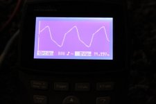
Up to app 9 or 10 kHz everything is ok. Above 10kHz the output signal get's distorted at high power. With 20kHz sine wave input at full power the output signal looks almost like a square wave. Switching back to 1kHz the output signal is again a nice sine wave.
At half power this isn't the case!
What could be wrong?
Today I did some measurements with my Aleph-X Blocks. They are build with the green DIY Audio boards. The circuit is scaled to app. 70 watts into 8 ohms.
Current Gain is set to app 65%.
Up to app 9 or 10 kHz everything is ok. Above 10kHz the output signal get's distorted at high power. With 20kHz sine wave input at full power the output signal looks almost like a square wave. Switching back to 1kHz the output signal is again a nice sine wave.
At half power this isn't the case!
What could be wrong?
........ Can this matching be done with a simple ohm meter at room temperature?
Thanks,
Eric
you can't parallel NTC's .
use bigger ones
.....
What could be wrong?
which output mosfets you're using , and what's Iq and PSU voltage ?
which output mosfets you're using , and what's Iq and PSU voltage ?
IRFP240
Bias is 3.1A
PSU Voltage is +/- 19V
AC current Gain is 69%
the problem shows only at high power
I have another Aleph-X (120W version with HK ruffneck board) and with this one all is ok.
Strange HF behaviour pics
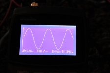
Output signal with sine input 2.5V and different frequency. Amp works app half power.
1st: 2.5V input (app half power) 1kHz
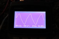
2nd: 2.5V input (app half power) 10kHz
3rd: 2.5V input (app half power) 20kHz
At low power level everything is ok.
Can anybody help?
Output signal with sine input 2.5V and different frequency. Amp works app half power.
1st: 2.5V input (app half power) 1kHz
2nd: 2.5V input (app half power) 10kHz
3rd: 2.5V input (app half power) 20kHz
At low power level everything is ok.
Can anybody help?
Attachments
What does the source signal look like at 2.5V (1kHz, 10kHz, 20kHz)?
Perfect sine from a HP 8903B Audio Analyzer.
I have 2 other Mono Blocks that do not have this problem.
8903B Nice toy.
What bias current are you running? And what does the signal look like out of the diff pairs on the input. Also what is the static DC offset on the outputs?
P.S. Even the first trace on the post above doesn't look too good.
What bias current are you running? And what does the signal look like out of the diff pairs on the input. Also what is the static DC offset on the outputs?
P.S. Even the first trace on the post above doesn't look too good.
Last edited:
8903B Nice toy.
What bias current are you running? And what does the signal look like out of the diff pairs on the input. Also what is the static DC offset on the outputs?
P.S. Even the first trace on the post above doesn't look too good.
Bias etc see #1995
Relative (static) DC is close to zero
Absolute DC is around 0.03V
Signal out of the diff. input I need to check
- Home
- Amplifiers
- Pass Labs
- Aleph-X builder's thread