looking good, glad you figured out the issue with the grounding and looking forward to your first listening test . I love the tidiness of your assembly - a far cry from my "entropic" work space.
Yippee!!!!
Looks marvelous!
I also have that Hakko desoldering tool. Extremely handy and well worth the $$
Best,
Anand.
Looks marvelous!
I also have that Hakko desoldering tool. Extremely handy and well worth the $$
Best,
Anand.
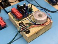
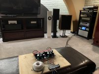
She’s on the test board now. Powered up and bias voltages are stable. Time to put some sound through it. Soooo…. Test it on the AJ? I’m a little tentative…
No attenuation on it yet, so planning to feed the input from one of my other preamps just to see if the gozinners and gozouters are doing their thing.
No attenuation on it yet, so planning to feed the input from one of my other preamps just to see if the gozinners and gozouters are doing their thing.
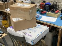
Attachments
Good luck Captain! Which transformer did you end up getting?
One of the things you want to be on the lookout for is oscillation. If you get unexplained noise/hum/hiss with the source feeding directly in (with no input attenuation) then you might want to look into adding 220R on the input as this design calls for the attenuator on the output normally.
If you are testing with another preamp and pot in front of it, you won't encounter it.
Last edited:
This one is an Antek 100VA 30x2. AS-1230. Series windings to get 60V.
Great thing about Antek for those of us in the US: great prices, fast shipping, consistent quality. Haven’t yet found a fault!
Great thing about Antek for those of us in the US: great prices, fast shipping, consistent quality. Haven’t yet found a fault!
Thanks for that tidbit. I haven’t got an output attenuator yet. Building a Muses electronic unit for this one and it still has some work to be done on it.
Good luck Captain! Which transformer did you end up getting?
One of the things you want to be on the lookout for is oscillation. If you get unexplained noise/hum/hiss with the source feeding directly in (with no input attenuation) then you might want to look into adding 220R on the input as this design calls for the attenuator on the output normally.
If you are testing with another preamp and pot in front of it, you won't encounter it.
Just in case you need it or want to read up on it. Thank Pinkmouse for the initial reporting and it was AlbertNL's posts that helped me track this down
AP1.7 Oscillation
AP1.7 Oscillation
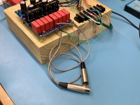
It plays! And it sounds quite nice and clean so far. Hard to tell its full potential since the gain is pretty darned low in its default configuration, even with the tail pot cranked all the way up. So I may put the pots back to center and change the input voltage divider configuration to let it stretch its legs a bit. So far I’m quite pleased. Well, pleased it works. 😀
Configurations so far include my Pioneer A/V acting as an attenuator ahead of the Aleph P as well as straight off the Modi DAC. So I know we need some more skinny pedal. Unbalanced input device is all I have at the moment. But I do have XRK’s BTSBs that I plan to do some buffering and SE-2-B conversions with.
Configurations so far include my Pioneer A/V acting as an attenuator ahead of the Aleph P as well as straight off the Modi DAC. So I know we need some more skinny pedal. Unbalanced input device is all I have at the moment. But I do have XRK’s BTSBs that I plan to do some buffering and SE-2-B conversions with.
Attachments
Last edited:
Love the breadboard - excellent for testing while you plan a permanent home for it!
Best,
Anand.
Best,
Anand.
I do have some cool plans for it! Project details soon...
Love the breadboard - excellent for testing while you plan a permanent home for it!
Best,
Anand.
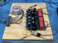
dB and I had a discussion about the current configuration and decided the next move should be to bypass the input voltage divider (I know ZM isn’t a fan) to see how things go. I lifted the grounded resistor and shorted the series resistor to configure it like the production AP high-gain setting. Definite has more gain than the previous configuration, but still lower than I thought it would be. I suspect it’s because of the SE input into a balanced circuit. I’ll see if dB has a balanced DAC he can loan me to test that theory.
That said, if I put the AP directly on the SE Modi DAC output and adjust the gain up a bit using the tail resistance…. Oh my…. Such clarity and spaciousness. Very nice sounding preamp.
I figured Rodrigo y Gabriela would be a good subject piece to try it out.
That said, if I put the AP directly on the SE Modi DAC output and adjust the gain up a bit using the tail resistance…. Oh my…. Such clarity and spaciousness. Very nice sounding preamp.
I figured Rodrigo y Gabriela would be a good subject piece to try it out.
Attachments


Last edited:
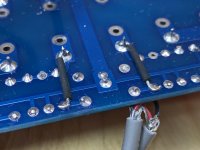
If I were going to eliminate the gain switch, I'd mount solderable turret standoffs in there so you could still easily change gain by just a quick resistor change. I have seen lots of electronics made this way. Some times its because a part in a circuit has to be selected in circuit for a given build. Other times its because of what I suggested in this post.
That’s actually one of the things that dB and I discussed. I’ll probably follow that experienced advice. This was a quick test, but it certainly needs a more permanent solution.
After a summer of outdoor and airplane projects, the winter has dragged me back inside to continue with audio projects. Following the advice of @Mark Allen , I have soldered in the appropriate sockets so that I can easily change gain as needed.If I were going to eliminate the gain switch, I'd mount solderable turret standoffs in there so you could still easily change gain by just a quick resistor change. I have seen lots of electronics made this way. Some times its because a part in a circuit has to be selected in circuit for a given build. Other times its because of what I suggested in this post.
Stacked as I plan to implement them, it’s time for the next phase of the adventure.

Chris,
Do you have a link for those “female type” resistor socket doohickeys (the one over LR32)?
Best,
Anand.
Do you have a link for those “female type” resistor socket doohickeys (the one over LR32)?
Best,
Anand.
- Home
- Amplifiers
- Pass Labs
- Aleph P v1.7 Build from Wisconsin