I would go rather for degeneration than choking input signal, for setting the gain
wasting signal is sacrilege in my book, and better to waste it with degeneration - changing transfer function, than killing it with attenuation
wasting signal is sacrilege in my book, and better to waste it with degeneration - changing transfer function, than killing it with attenuation
Would you suggest using one of the higher-gain input options other than 1.3dB? A couple of others have suggested that perhaps the high gain that this preamp provides might be too much for an AJ. Unless of course I can provide enough degeneration to bring it back down. Although it would be pretty sweet for an F4. 🙂
I would go rather for degeneration than choking input signal, for setting the gain
wasting signal is sacrilege in my book, and better to waste it with degeneration - changing transfer function, than killing it with attenuation
easiest to check it in vivo
being ages when I was playing with 1.7- like circuits and sleepy now to calc anything
if you don't need gain, be done with decent buffer
if you prefer some gain , plus some sonic flavor, just play with degeneration and set it for your liking
easy - either change trimpot to 10K and fiddle with, or put 1pin sockets for one resistor and have fun with re-inserting procedure
in case that you don't have a scope, easy done with DVM set to AC - feed input with sine of 400-1KHz and measure in & out - it'll be precise enough
hope you have proper balanced source(s) - only then going all balanced is beneficiary
Slowly building my arsenal 😉 Appreciate your expertise. No need to beat up your brain this late at night. In circuit fun it shall be.
hope you have proper balanced source(s) - only then going all balanced is beneficiary
Last edited:
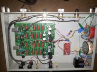
I built a P-1.7 about 5 years ago and it's a really good sounding piece. Mine was on a different board... what ever was available at the time and before the onslaught of Chinese boards. I turned it on when it was basically done, and never turned it off those 5 years till I moved to Nashville... except to change the capacitors to WIMA. They sound a lot better than the originals I used.
Attachments
Last edited:
Very nice 🙂
Cant wait to hear this one. I expect it to be the hub of the whole kit and caboodle. It seems like a great choice.
Cant wait to hear this one. I expect it to be the hub of the whole kit and caboodle. It seems like a great choice.
I built a P-1.7 about 5 years ago and it's a really good sounding piece. Mine was on a different board... what ever was available at the time and before the onslaught of Chinese boards. I turned it on when it was basically done, and never turned it off those 5 years till I moved to Nashville... except to change the capacitors to WIMA. They sound a lot better than the originals I used.
I drove Krell Klilone KSA-50 and 100 with it as well as a pair of monoblock Aleph 2's. Dynaudio speakers...
Would you suggest using one of the higher-gain input options other than 1.3dB? A couple of others have suggested that perhaps the high gain that this preamp provides might be too much for an AJ. Unless of course I can provide enough degeneration to bring it back down. Although it would be pretty sweet for an F4. 🙂
I have P 1.7 with AJ at Monacor Aspera speakers (4 Ohm / 88 dB /1 W/1 m)
Having gain at lowest position is loud enough for a 16m^2 room.
For F5 i prefer more gain.
Maybe with more sensitiv Speakers gain at lowest position could be to much.
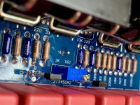
Gain adjustment ist done like suggested at the R. Stens P1.7 build
2k Resitance in Parallel connection with a variable resistance.
In my case a 12 Step Lorlin switch with resistors.
As it.is my practice to answer all emails, it is possible that yours got lost.
So you understand, I don't get upset about diy cloning for several reasons:
1. It's DIY
2. I don't need the money.
3. Could be worse - they could be cloning someone else.

🙂
All was working well with input and output VAC being shown on my DMM with input from the sig-gen. Good start! Then I attempted to connect my o’scope grounding lead to the board and the smoke gods got angry. The boards are floating ground right now, so presume my scope ground caused an imbalance or surge of some sort and took out at least one, probably two bridge diodes. Reckon I’ll try a CL-60 to ground to equalize things and try again after I replace the bridge diodes. Surrounding circuits test good compared to the good board.
Attachments
I built a P-1.7 about 5 years ago and it's a really good sounding piece. Mine was on a different board... what ever was available at the time and before the onslaught of Chinese boards. I turned it on when it was basically done, and never turned it off those 5 years till I moved to Nashville... except to change the capacitors to WIMA. They sound a lot better than the originals I used.
interested in your pot set up. before the amp?
just for my curiosity, why would you need that extra high gain from preamp like this when your amplifier only need 2V input like regular Papa Amp? stay aside from F4 type amplifier with no gain
i currently use dcb1 after my dac where rarely 50% volume is occupied. i have amb a20 board that was salvaged from headamp, it is set into 6x gain but still haven't got it's usage yet for preamp
i think the only possible one is for SIT L'Amp that i build where it requires 5V input for full swing
i currently use dcb1 after my dac where rarely 50% volume is occupied. i have amb a20 board that was salvaged from headamp, it is set into 6x gain but still haven't got it's usage yet for preamp
i think the only possible one is for SIT L'Amp that i build where it requires 5V input for full swing
As you described, it can be very useful for a current gain amp like the F4. The input flexibility is also useful. With adjustable input gain, as I understand it you can set it up to run just about any amplifier you can think of. I’m currently using an Aleph J, which would probably not benefit from the high gain, which is why I have it set to the lowest setting (1.3dB). But if my needs change, then I will have that flexibility. Additionally, it’s a balanced device both input and output. So I am building an environment to support that. Just my choice. 🙂
just for my curiosity, why would you need that extra high gain from preamp like this when your amplifier only need 2V input like regular Papa Amp? stay aside from F4 type amplifier with no gain
i currently use dcb1 after my dac where rarely 50% volume is occupied. i have amb a20 board that was salvaged from headamp, it is set into 6x gain but still haven't got it's usage yet for preamp
i think the only possible one is for SIT L'Amp that i build where it requires 5V input for full swing
Last edited:
wait what??? adjustable gain? never thought that this alephP has this feature, i thought it's not good choice for adjustable gain (read it somewhere)
nice feature
nice feature
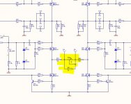
Yes sir. Input voltage divider has a variety of combinations at the input that allows overall gain adjustment from 1.3dB to 15dB gain. If you check the service manual for it, or see the schematic in the first couple of posts, you’ll see the official circuit has DIP switches to enable/disable input resistors, changing input levels. Or if you’re ZM, wastes signal before it gets to the amp stage. 😛
Last edited:
currently my dcb1 has 3 output : direct to J2, to subwoofer, and to minidsp, while amb a20 might have it's place later.
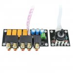
due to subwoofer output is mandatory, i'm planning to use this rca input selector to become output selector. so dcb1 will only see 2 output in paralel instead of 4. at the same time i will only listen to 1 main speaker setup
due to subwoofer output is mandatory, i'm planning to use this rca input selector to become output selector. so dcb1 will only see 2 output in paralel instead of 4. at the same time i will only listen to 1 main speaker setup
Attachments
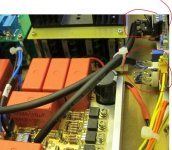
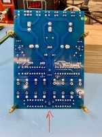
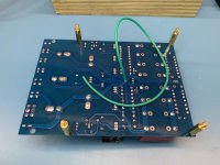
I repaired the damaged bridge tonight. One diode open and another shorted. This damage occurred when I hooked my o'scope ground lead to the ground plane of the board. Sparks and smoke, then no work. I presumed a current imbalance or some such thing because the ground was floating.
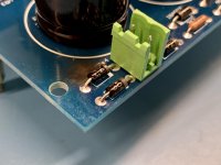
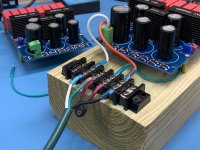
After replacing the parts, I set off on getting a proper ground on the board and attached a ground wire to the star point of the ground collection. The arrow indicates where the signal and power ground come together at the edge of the board. On my test rig, I attached a CL-60 between earth ground from the power outlet/variac and the circuit board. This would replicate how a typical Pass power supply configuration would be in my best estimation.
Ready to test, I set the variac on zero, turned it on, and started to dial it up. No sooner did the knob come up off the bottom than the GFCI popped on the outlet to which the variac was connected. Just for the sake of testing, I moved it to a different outlet on a different electrical panel and the same occurred. If I disconnect the ground, all works as it should and voltages are normal.
So this grounding configuration is puzzling. All the caps, transistors, and FETs are installed in the correct orientation, so nothing there that seems out of sorts. Quite ponderous, indeed. I welcome comments from PSU experts.
Attachments
you can solve that in somewhat dangerous and in non-dangerous way
either remove safety earth conductor of your scope (so it is floating), or feed it through mains isolation xformer (so it is floating)
either remove safety earth conductor of your scope (so it is floating), or feed it through mains isolation xformer (so it is floating)
- Home
- Amplifiers
- Pass Labs
- Aleph P v1.7 Build from Wisconsin