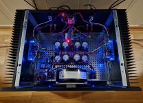
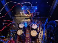
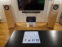
Here are some photos of my finished Aleph Jzm. I had to replace the speaker terminals because the ones I initially installed didn't work well with banana plugs. The new ones are much better. The bias is stable at 460 mV ± 3 mV, and the offset is less than 10 mV (with the lid on).
It sounds beautiful and is very quiet.
However, it does run hot! I measured 50-55 °C on the heat sinks, which I suppose is normal. The transformer, a 400VA unit from Toroidy, also gets quite hot. I measured it at about 60 °C. Should I be concerned about this? There is no smoke or strange smells.


It sounds beautiful and is very quiet.
However, it does run hot! I measured 50-55 °C on the heat sinks, which I suppose is normal. The transformer, a 400VA unit from Toroidy, also gets quite hot. I measured it at about 60 °C. Should I be concerned about this? There is no smoke or strange smells.


I mailed and asked Toroidy about transformer temperatures when i had built my Aleph J:s. This is what they said:
”Normal operating temperature is up to 70*C. Temperature above 90*C may lead to failure.”
🎷🙂🎸
”Normal operating temperature is up to 70*C. Temperature above 90*C may lead to failure.”
🎷🙂🎸
Here are some photos of my finished Aleph Jzm. I had to replace the speaker terminals because the ones I initially installed didn't work well with banana plugs. The new ones are much better. The bias is stable at 460 mV ± 3 mV, and the offset is less than 10 mV (with the lid on).
It sounds beautiful and is very quiet.
However, it does run hot! I measured 50-55 °C on the heat sinks, which I suppose is normal. The transformer, a 400VA unit from Toroidy, also gets quite hot. I measured it at about 60 °C. Should I be concerned about this? There is no smoke or strange smells.
The 50-55 deg C is not too bad, but a bit on the high side. Reducing the bias will help; this will also cool down the transformer.
The heatsink size is too small in my opinion. The heatsinks are already minuscule by default (I always thought their size was too small for the intended purpose), and only one of those heatsinks per side is not what I'd use for my build.
Also, the way you mounted the transformer (the L-mounting plate) blocks the bottom plate vents... Toroidy sells a transform mounting plate that lifts the transformer from the bottom plate.
I implemented a little trick with the top cover... I mounted the top cover on my build using 4 rubber feet; the use of the brass distancers ensures good ground uniformity (I scraped the paint from the top cover at 2 places where the brass distancers touch the top cover). It works well - it lets the inside hot air escape much easier than the flat-mounted top cover.
Aren't the rubber spacers superfluous with the brass extenders?I mounted the top cover on my build using 4 rubber feet
I spent a bit of time and thought it through... I tried different options and combinations.
Primarily, the top cover resides on 4 rubber feet. This dampens the resonances/ringing as well. The Modushop case, apart from the minuscule heatsink size, rings/resonates like the church bells at loud listening levels, and that needs to be tamed. Hence the 3 conical, hollow ceramic feet supporting the full weight of the amplifier you can see in the photos - 2 at the front and one at the back right underneath the transformer.
I used 2 brass distancers to ensure good electrical connectivity... I suppose one distancer would be enough for the intended purpose, but I chose two because... it looks symmetrical 🙂. Also, 1 brass distancer (in one corner only) would not secure the top cover firmly in place...
4 brass distancers would be too much; this would defy the idea of resting the top cover primarily on rubber feet.
Yes, I may very well do that. Although it's reassuring that Toroidy considers anything below 70 normal ...make Babysitter
I do wonder how hot the commercial Pass/ First Watt Aleph-type amps get. The First Watt Aleph J chassis doesn't seem to have a lot of ventilation, judging by photos online.
with a 24V battery?
yeah, but with 2 of them
stacked, so you have +24, common (GND) and -24V
Aleph J is Biiiiig ACA
and be sure that batteries are big ones, Iq is substantially bigger than with ACA
Yes, so car size batteries would not be excessive. A pair of 12V batteries in series for each rail.Aleph J is Biiiiig ACA
and be sure that batteries are big ones, Iq is substantially bigger than with ACA
Then some nice motor run caps on each rail, independent to each channel to provide a low impedance power source.
Yup, but you would have to replace for new one every lp.Any chance I could run the Aleph Jzm with a 24V battery? Any comparisons to ACA?
I feel like four absorbent glass matt lead acid deep cycle marine batteries at 55Ah can probably get through 2 LP's. Not cheap though.
I'm curious if the plan is to bring the Aleph Jzm out on the pontoon boat? Tuning while toonin'! Good times.
I'm curious if the plan is to bring the Aleph Jzm out on the pontoon boat? Tuning while toonin'! Good times.
Hey Everybody!
One channel works fine (offset <5 mV; bias at 461 mV), but this one won't go below 800 mV bias. LEDs light up and DC offset can be controlled, but bias is stuck between 800 and 850 mV. Input is single-ended. Any obvious errors?

One channel works fine (offset <5 mV; bias at 461 mV), but this one won't go below 800 mV bias. LEDs light up and DC offset can be controlled, but bias is stuck between 800 and 850 mV. Input is single-ended. Any obvious errors?
usual drill
inspection of all positions for proper part/value/orientation - it helps having one channel operative, so look for differences
inspection of all solder joints for proper done/no shorts
inspection of all positions for proper part/value/orientation - it helps having one channel operative, so look for differences
inspection of all solder joints for proper done/no shorts
it is explained in Build Guide, but worthy repeating - check that mosfets are not shorted to heatsink
I was absolutely certain there were no shorts, as I have made that mistake in the past. Measured all devices with reference to ground, before and after soldering them in place.
I was already pretty sure I'd have to go over everything with a fine-tooth comb, but the reason I posted was that I was hoping that there might be an obvious error, based on the 800 mV bias measurement--sheer hopeful laziness on my part. But I'll pull out the board and go over everything again.
Thanks ZM for your design and help.
I have two 4.5Ah NiMH batteries sitting around (can’t sell them). I’m trying to find a use for them. But it sounds like these aren’t enough. Thanks anyway.yeah, but with 2 of them
stacked, so you have +24, common (GND) and -24V
Aleph J is Biiiiig ACA
and be sure that batteries are big ones, Iq is substantially bigger than with ACA
- Home
- Amplifiers
- Pass Labs
- Aleph Jzm