bias is stuck between 800 and 850 mV
I don't see any stuffing errors (all that's easy to check are the resistors that are visible in the photo) and the pot markings. Your soldering looks clean. It's still worth checking all parts again.I was hoping that there might be an obvious error, based on the 800 mV bias measurement
It would be an odd issue, but after triple checking all your parts, I'd check TP2. All builds will vary, but you should have had about a 250mV range between ~350mV and ~600mV across R29. Having the voltage across R29 respond, but not respond more than 50mV from 'click to click' on TP2 is of interest.
Check the solder joints on the pot. If it looks fine... you may do a quick check to see if it's working properly => you have the full range of resistance when you turn the pot from 'click to click'. What I would do in your situation is put a probe on R21 (the side closest to TP2, the right side) and R23 (the side closest to C4, the right side) and measure the resistance from click to click. If it's not 0 ohms to roughly 50k ohms, I'd remove the pot and check it.
Mighty ZM may have some voltage checks to offer after you review to help narrow further.

curious on the pcb, what are all the zones of feedthroughs? to have a large area of copper but lower capacitance?
I believe you are referring to the tightly spaced thru hole "vias", often called "thermal vias" when packed together, which can help with heat dissapation. At least I think that's the purpose.
They also looks pretty cool all golden and shiny.
They also looks pretty cool all golden and shiny.
They can help with efficient power distribution by connecting the power planes on both sides of the board. Lots of copper as you say, where there would have been just FR4 material otherwise. There may be an added surcharge from the PCB house in some cases since it makes the design more expensive.
If I'm feeling ambitious, a trick I do from time to time is remove the solder mask and solder a fairly heavy gauge supplemental bus wire onto a long trace that carries heavy power or signal current to reduce the resistance.
If I'm feeling ambitious, a trick I do from time to time is remove the solder mask and solder a fairly heavy gauge supplemental bus wire onto a long trace that carries heavy power or signal current to reduce the resistance.
Use copper desoldering braid instead of wire. It's thicker and flatter and more conductive and it looks a lot more sexy too.If I'm feeling ambitious, a trick I do from time to time is remove the solder mask and solder a fairly heavy gauge supplemental bus wire onto a long trace that carries heavy power or signal current to reduce the resistance.
what are all the zones of feedthroughs?
often using those, just to remind me visually of all times when I was walking on the water
of secondary importance - increases effective copper thickness by much
Just a quick post to say I have finally built a pair of these boards after sitting on them for a couple of years…
Worked great, first time, biased perfectly, very low/stable offset. Brief panic on first speaker connection - mixed power gnd/-ve rails after “tidying up the wiring”(😮!!!), but realised after no more than 2 seconds, and no harm done thankfully!
Running very low bias, just over 1A Iq, because I have totally inadequate heatsink. That runs it about as hot as I want to go, works out to ~15w into my RS225/10F DIY speakers from the other thread. They are in a small snug room, and honestly, this amp makes them sing so musically. It’s not going to create a visceral enormous presence of a concert orchestra, but for lower level evening listening, I cannot overstate how lovely this combination is. Musical, tight, punchy, open, clear, smooth. For a small room, I can’t see how there is much room for improvement.
A top design/project/amplifier!
A top design/project/amplifier!
Blame Pa
In case anyone is looking for a comparison at some point in the future: this replaced an F5 in my rack. My PSU is outboard, so that stayed the same, speakers unchanged.
Swapping from the F5 to this - immediately there was a much greater sense of ease. The sense of space improved. Somehow it felt like distortion and grain had just been removed. I would say this is a significantly better choice of build than an F5. I’m at 15w into 8ohm. But double up the Mosfets and have proper heatsink, and it’ll do 50w.
Next for me is a BA3. Let’s see if that can possibly be as good as this!
F5, BA3, Aleph J ........... if all made properly, choice is matter of task at hand and personal preferences
Finally, no more procrastination!
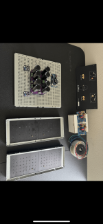
PSU done Amp boards almost done.
PSU mounted with rectifiers.
Waiting on 3d printed bits to get finished. I also am awaiting a new variac.
Also rear panel has all the bits mounted.
Much to do so little time!
PSU done Amp boards almost done.
PSU mounted with rectifiers.
Waiting on 3d printed bits to get finished. I also am awaiting a new variac.
Also rear panel has all the bits mounted.
Much to do so little time!
dammit!
lip up, 7-10mm spacers (longer screws, 2-3pcs of M5 nuts as spacers), mains wires bellow
lip up, 7-10mm spacers (longer screws, 2-3pcs of M5 nuts as spacers), mains wires bellow
@uptownsquash - I'm not disagreeing with his-mightiness... just adding a POV.
With that particular PSU... your mains wiring can be quite short. It does not run all the way from the back of the chassis up to the front. It simply runs a few inches from the PEM to the PSU board.
So... flipping the panel to leave sharp edges upward and leave more space to put mains wires between the bottom panel and perforated plate in a Modushop chassis is a bit less critical with this PSU layout. As an example with a typical layout seen with the Universal PSU boards, I almost always flip the baseplate.
The AJ I built for the guide was absolutely hum free with sensitive speakers, and I didn't flip the plate.
Note - I can't quite tell what the blue module is, but the two relays? make me think it's a speaker protection board. You probably wouldn't want your mains wires running right under it (unless separated by the perforated plate).
YMMV.
- Home
- Amplifiers
- Pass Labs
- Aleph Jzm