carpenter said:Am I in the ballpark?
sorry - I meant on CCS which you can see in Shunty , not
 😉
😉it's here :
(EDIT: you're really nutz
 ........ I can't understand what you are doing with these two little bjts there ..... )
Attachments

Zen Mod said:
you're really nutz
Call me grasshopper? 😀
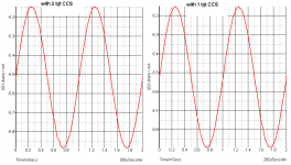
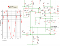
Edit: the little change I made (adding the second bjt) formed a more attractive (fuller) looking sine wave when I checked the current in the drain pin of the diff pair jfet.... there was a little distortion in the first peak, but it smoothed right out by the second.
That's why I thought I might be on to something.
Attachments
Hi Choky,
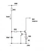
I incorporated your last diagram to my schematics and it gives stronger current: 10mA....
On my next brake, I'll play with the values and see if I can drop that current down to 6mA.
Happy 🙂
I incorporated your last diagram to my schematics and it gives stronger current: 10mA....
On my next brake, I'll play with the values and see if I can drop that current down to 6mA.
Happy 🙂
Choky, as drawn, does your 100 ohm pot bypass your 82 ohm resistor altogether?
I tweeked it and ran the pots center point to the top of the 82 ohm resistor.
I tweeked it and ran the pots center point to the top of the 82 ohm resistor.
carpenter said:Call me grasshopper?
Looks like you've got a long way to go before you turn Kwai Chang Caine.
jacco vermeulen said:
Looks like you've got a long way to go before you turn Kwai Chang Caine.
me baby grasshopper?
carpenter said:Choky, as drawn, does your 100 ohm pot bypass your 82 ohm resistor altogether?
I tweeked it and ran the pots center point to the top of the 82 ohm resistor.
sorry .......... that's hurry , but you're smart enough for two of us
Attachments
Zen Mod said:
sorry .......... that's hurry , but you're smart enough for two of us
Like I always say--you're a peach!

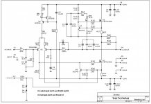
It might be of topic (haha), but I have modified one of my old creations to Aleph J, but the bias current seems to be too high. I'm suspecting that the value of R27 should be much lower than 68k.
My reasoning:
If Q4 is to be kept active, it must have roughly 0.7 Vbe drop, and the drop over R16 can be 0.5V for the sake of the argument, which leaves 0.2V across R15 - right?
If that is true, and the drop Vce is 4.3V, the value of R27 can be calculated from this equation:
(4.3V-0.7V)/R27=0.2V/R15
=>
R27=18k 😕
And it must be even lower, if the bias current should be lowered below 500mV.
I have just read through the thread and it doesn't seem like too many people have reported their bias currents, but 540mV which I read somewhere is not too far away from the figures I measure 600mV.
I have lowering R27 to 33k, which yielded approx 500mV - still to high for my sink.
cviller said:It might be of topic (haha), .......
just shoot on same Ugs voltage for lower mosfet bank , as it were in your "previous incarnation" .
dunno - maybe this old file (written when I was just young cathode follower
) will be usefulAttachments
Babbelfish -> fishamp -> aleph j -> babbelfish.... 😀
After watching columbo last night I did some more DC analysis (based on my previous assumptions), but with the difference that I place R27 the same way as in babbelfish and other alephs, which is between R25 and F26 instead of between R26 and Q4c.
With this change, the voltage drop across R27 is obviously much higher, hence the current required for feeding a voltage drop of 0.2V on R15 is much less. In fact, I calculated R27 to be 83k, which seems to be quite spot on, since in the calculation I aim for 500mV on R16 is higher than stock Aleph j, so 68k will be perfect for the 3-400mV range.
Is this simply a small typo in the schematics?
After doing these calculations, I have started to like the placement of R27 in the aleph j schem posted more, since this is not depended on rail voltages (try to do the dc calculations), and R27 is effectively cut of from the music going on on the node between R25 and F26. However, to be current limiting the value of R27 must be in the 10k-20k range.
cviller said:Babbelfish -> fishamp -> aleph j -> babbelfish.... 😀
cviller , can you post exact schematic ;
I'm somewhat lost in nomenclature , without knowing what's exact schm .
just in case - look at this , and then tell me where is difference
Attachments

I am looking at papas last (I think) Aleph J schematics, in this post:
http://www.diyaudio.com/forums/showthread.php?postid=1343785#post1343785
Schematics:
http://www.diyaudio.com/forums/attachment.php?s=&postid=1343785&stamp=1194303063
The purpose of R13-WR2 in your schematics is the same as R27 in papas, but look where leg with the highest potential is connected - very different indeed.
cviller said:I am looking at papas last (I think) Aleph J schematics, in this post:
http://www.diyaudio.com/forums/showthread.php?postid=1343785#post1343785
Schematics:
http://www.diyaudio.com/forums/attachment.php?s=&postid=1343785&stamp=1194303063
The purpose of R13-WR2 in your schematics is the same as R27 in papas, but look where leg with the highest potential is connected - very different indeed.
yup ;
I saw that ( we probably discussed that in thread already ) - again just after posting these two schematics ;
anyway - I dunno can we hear any difference between "old" and "new" type of connection ;
I'm pretty sure that I can't hear the difference 😉
You can feel the difference... I have now changed R27 to 12.7k which gives me 370mV. With 66k I get 600mV.
Now the thingie is humming along. It sounds quite nice, but I'm not in the mood for comparison listening tests... have to watch le tour 😉
I'll let it play the afternoon to make sure I it doesn't start doing nasty tricks.
The gain does however seem to be lower than the babbelfish I build some time ago, and also this amp which I have converted to almost stock aleph j.
I had to go a little lower on R8, so I inserted a 909R and a 100R pot to get the dc down in the range of 1mV. The biggest change I did was to use 12.7k in the place of R27 in order to get down to 370~380mV across source resistors.
Btw, turn on thump is not bad at all! 😎
All that distortion makes you think...
Right now I am listening to the alpeh j I made for my brother (lucky bast**d) 😉
I got it back for a short while because he wanted to move it to another chassis (pictures soon perhaps), so he could fit it in some fancy shelf - oh vanity... 😉
Well, I have been using the F4 as my primary amp for more than a year now, and I have been very happy with the sound. But after moving the boards to the new chassis, I am listening to the aj and I must say that it sound awfully good.
The bass is much tighter on the f4 for sure, but there is just so much interesting stuff happening with the aj. I know this is the second vs third order harmonic distortion discussion, but what I experience is that after listening to third for a while time, aj sound really musical and nice as a change.
I find that the musical collection narrows down, when listening to the aj, because drums that are not on the beat annoys mere more with this amp (strangely enough, I would have guessed the opposite). MP3 cd's are also more unbearable to listen to - this is however not really a problem but just an observation.
The funny thing is that listening is so subjective - for a while you feel that A is the perfect thing for you, but then you hear B which does a few things very good which is lacking in A, but after getting used to B, A suddenly makes you see what is lacking in B....
Hurray I can keep building amps and feel I get something new every time!!!! 😀
- Home
- Amplifiers
- Pass Labs
- Aleph J Schematic