carpenter said:How about I post what I'm studying now? Your comments are valued; I'm not intentionally playing games. Sometimes I'm just a little dense in the head:
well - I didn't say that I don't like you games

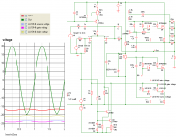
anyway - what's role of these Q10 and Q11 , across R34 ?
something is redundant ........ I bet both Qs .....please - go back and re-read several posts in Aleph J thread where EUVL's proposal is ..... there is exact ( and almost sole) concept how that can be made ;
now you're trying same few things I already drew ..... wasting volts in negative PSU..........
Zen Mod said:now you're trying same few things I already drew .....
Why, that's a fine compliment. 😉
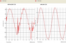
Q10 and Q11? The sim really likes those jfets! The current goes up to 6mA with and practically nothing without them. In fact, the output from the diff pair is much smoother with them, as well. I'll study Patrick's ideas, but I don't think you're so far from the bulls-eye. 🙂
Attachments
carpenter said:
Why, that's a fine compliment. 😉
Q10 and Q11? The sim really likes those jfets! The current goes up to 6mA with and practically nothing without them. In fact, the output from the diff pair is much smoother with them, as well. I'll study Patrick's ideas, but I don't think you're so far from the bulls-eye. 🙂
either I'm dumb or your sim is 😀
try this one ;
it's not A J , but it's X-ed
Attachments
Zen Mod said:
either I'm dumb or your sim is 😀
try this one ;
it's not A J , but it's X-ed
I added several pics to my previous post, Choky.
I'll sim your drawing and see what it does. This is the easiest way for me to learn.
carpenter said:Latest effort:
R34 - 10K !!

you really make me that I must draw something ( by hand) ........
but later ........
Zen Mod said:
R34 - 10K !!
you really make me that I must draw something ( by hand) ........
but later ........
Stock 1K for R34:
Attachments
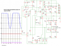
carpenter said:I raised R19 to 150K; that brought back a sine wave... What do you think?
are you sure that you don't have some Serbian ancestors ?
sometimes you're same as fast & stubborn as serb
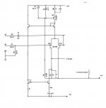
look here - just as example ;
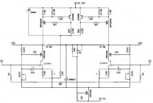
LU gate MUST BE REFERENCED TO - 24V , where also source must be connected ,via source resistor ;
that means - LU is self- biased ,same as dreky triode /pentode , whatever ........
point is - you have 1K in drain of input Jfet ; 1K is adequate value - as load for that Jfet , and also adequate regarding AC amplitude across it for LU's gate modulation ;
you can't put there every bloody value you can imagine
CCS , bellow that 1K resistor is there , to achieve 0V DC across 1K resistor ..... in common words - to RELOAD it - DC wise .......
edit - here at my place is p[retty late ....... so - it's completely possible that I made some drek in that schematic ............
and - it can be simpler at least 75% ( without mirrors - just CCS bellow -25V )...... but - without testing I can't say that simpler should be better
Attachments
Zen Mod said:
are you sure that you don't have some Serbian ancestors ?
sometimes you're same as fast & stubborn as serb
My ancestors originated from Holland......
carpenter said:
My ancestors originated from Holland......
hehe
that xplains everything ......... you and Jaccovitty will eat my liver .......

Zen Mod said:
hehe
that xplains everything ......... you and Jaccovitty will eat my liver .......
Only with onions and lots of garlic!!!!!!!!!
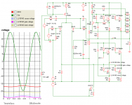
carpenter said:With Choky's instructions


almost fast as Pony Express !
make that R1 - pot of 47E
edit :
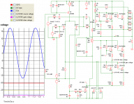
now - because of better tempco - replace both CCS-es ( Q3 and Q10) with two bjt CCS (look at Bab schm)
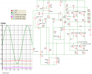
carpenter said:Here's a start:
now replace Q10 CCS with two bjt CCS ; look at
 schmtc for inspiration
/point is that two bjt CCS have much better tempco than variant with one bjt /
- Home
- Amplifiers
- Pass Labs
- Aleph J Schematic