and convince myself that all the mods make it "better". Don't we all?
Yes we all sure do. 🙂
Thats why we all MUST take ALL music playback system tweaking and modification tips with a truckload of Clint Eastwood cool.
And that includes our own ”rock solid” tweaking tips.
🙂🙂🙂
Last edited:


But:
Exactly At WHAT point on the modification journey is the amplifier no longer really the good old smooth yet detailed sounding Aleph J?
In this example it’s very easy to answer -
Upon either the 1) Jfet input stage being removed and/or the 2) Aleph current source being removed.
Without the first it’s not a “J”, without the 2nd it’s not an “Aleph”.
Mods, tweaks, and other such stuff won’t make as much difference as the removal of either of those two elements.
Wayne BA2018, BA3 and Holoaudio Serene. Currently in use is Serene. I like the most the sound ofAleph J with balanced input.Your preamp for j? Please.
Please note that Serene is DC coupled. So if you have any DC offset coming from DAC or other source it will be transferred via Serene and amplified by Aleph J. This is why I have speaker protector boards and check DC offset on speaker terminal on regular basis. In my case it is between +-20mV.
I can easily see a tiny DC offset coming from the source just by muting and unmuting the preamp with multimeter connected to the speaker binding posts of Aleph J.
Nice pre-amp you have there... I have May DAC - stunning.
Yeah, going fully differential (balanced) is the way to go.
In addition to the list of mods in post# 10195, you could also try carbon-film gate stoppers.
What speakers do you use?
Yeah, going fully differential (balanced) is the way to go.
In addition to the list of mods in post# 10195, you could also try carbon-film gate stoppers.
What speakers do you use?
Hi,
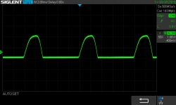
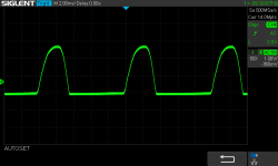
I noticed an irregular, high frequency "chirping sound" coming from both new trafos. I thought that it would go away after a day or so. It did not. I contacted the producer (toroidy.pl).
I was informed that happens usually when the current peaks are too big due to high capacitance of first CRC capacitor bank (2x 33mF in my case) and relatively low resistance of primary and secondary windings (it is my simplification of entire comprehensive explanation provided).
Possible solutions:
Due to the lack of smaller capacitors, chokes and limited test environment, I went with the second solution.
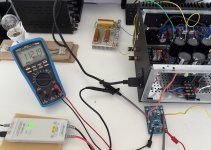
Only one rail (positive) was used with a dummy load of 18 Ohm.
I measured a voltage drop on one of CRC resistors (0R47) when the amp was optional 0.230V.
With dummy load voltage drop was 0.168V.
That gives 1.37 ratio between regular Aleph J current draw from PSU versus dummy load current draw.
Test 1:
0.33 Ohm resistance between bridge and PSU.
Max current = 2.0V / 0.33Ohm = 6A
The chirping sound is practically gone.
Additionally, a small hum that was present at Antek and Toroidy trafos was not audible (I had blamed the DC on mains for that).
Test 2:
0.5 Ohm resistance between bridge and PSU.
Max current = 2.7V / 0.5Ohm = 5.4A
Similar results.
Assuming that the relation between installed resistance and the peak current is linear, I did the following extrapolations from above 2 tests:
I consider 2 resistors 1 Ohm (25Watts), between each bridge and the PSU terminal going to positive and negative rail.
https://mou.sr/4h23bT3
That should solve the issue, reduce the current peaks from almost 10A to 5A. My rails are +- 26 volts, so I can drop 2-3V easily. Trafo secondaries are rated 6.15A.
Any thoughts or mistakes in the above?
How about 1 Ohm resistor 50W, where 2 wires from rectifiers are connected to one end of resistor and the second and to the common ground input of PSU?
I noticed an irregular, high frequency "chirping sound" coming from both new trafos. I thought that it would go away after a day or so. It did not. I contacted the producer (toroidy.pl).
I was informed that happens usually when the current peaks are too big due to high capacitance of first CRC capacitor bank (2x 33mF in my case) and relatively low resistance of primary and secondary windings (it is my simplification of entire comprehensive explanation provided).
Possible solutions:
- lower capacitance in first caps bank (I do not want that)
- additional resistor (in my case between bridge rectifier and CRC)
- additional choke
Due to the lack of smaller capacitors, chokes and limited test environment, I went with the second solution.
Only one rail (positive) was used with a dummy load of 18 Ohm.
I measured a voltage drop on one of CRC resistors (0R47) when the amp was optional 0.230V.
With dummy load voltage drop was 0.168V.
That gives 1.37 ratio between regular Aleph J current draw from PSU versus dummy load current draw.
Test 1:
0.33 Ohm resistance between bridge and PSU.
Max current = 2.0V / 0.33Ohm = 6A
The chirping sound is practically gone.
Additionally, a small hum that was present at Antek and Toroidy trafos was not audible (I had blamed the DC on mains for that).
Test 2:
0.5 Ohm resistance between bridge and PSU.
Max current = 2.7V / 0.5Ohm = 5.4A
Similar results.
Assuming that the relation between installed resistance and the peak current is linear, I did the following extrapolations from above 2 tests:
- 0R (no resistor) - peak current 7.16A with dummy load. Considering the load factor or 1.37, there should be 9.8A peaks when Aleph J is working
- 1R - peak 3.64A with dummy load, 4.95A in Aleph J.
I consider 2 resistors 1 Ohm (25Watts), between each bridge and the PSU terminal going to positive and negative rail.
https://mou.sr/4h23bT3
That should solve the issue, reduce the current peaks from almost 10A to 5A. My rails are +- 26 volts, so I can drop 2-3V easily. Trafo secondaries are rated 6.15A.
Any thoughts or mistakes in the above?
How about 1 Ohm resistor 50W, where 2 wires from rectifiers are connected to one end of resistor and the second and to the common ground input of PSU?
Attachments
lower capacitance in first caps bank (I do not want that)
and this is exactly what you need to do
make first C smaller and second C bigger
next time, if you prefer brute force, learn from old saying - don't use force, use bigger hammer
so, bigger donuts

Hehhee, sledge hammer.
Unfortunately, psu designer shows no big improvement if one cap from the first bank is removed…. Resistors would be easier and cheaper than recapping, not mentioning bigger irons. 🤣
Unfortunately, psu designer shows no big improvement if one cap from the first bank is removed…. Resistors would be easier and cheaper than recapping, not mentioning bigger irons. 🤣
Hehhee, sledge hammer.
Unfortunately, psu designer shows no big improvement if one cap from the first bank is removed…. Resistors would be easier and cheaper than recapping, not mentioning bigger irons. 🤣
What is the model number of the toroids you used?
Another one come to life and singing sweetly🎵🎶
Thank you linesmen, thank you ballboys - please help yourselves to a pat on the back from me and my happy ears and my unhappy neighbours 🫡
Thank you linesmen, thank you ballboys - please help yourselves to a pat on the back from me and my happy ears and my unhappy neighbours 🫡
I am finishing up the first channel of my monoblock Aleph J build. My speakers are listed at 4 ohms (Martin Logen ESLs), so I have fitted a couple of Noctua fans to the heat sinks to allow a higher bias. A thermostat turns the fans on once the heat sink reaches 40C/104F. With the bias at 1.17A, the heat sink stabilizes at 45C/114F. I am tempted to go a little higher. I see that some here have advocated for 2 to 3A for 4 ohm speakers. Any suggestions?
Attachments
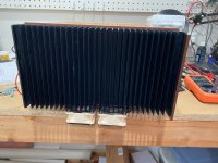
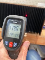
I run 2A bias per each AMP PCB. Dynaudio Contour 30i. Before that, I used Contour 1.3. Both are 4 ohms. The new Contour 30i floor standers sound scary good, but this is with a Deluxe 5U chassis. I also paid a bit of attention to the overall layout/internal 4mm² (#12AWG) wiring to ensure it stays short... and I did a few other little mods/tweaks. The sound pressure I can generate with new speakers and my Aleph J is frightening... In your case, I think 2A might be a bit too much for that single heatsink you've shown in the photos... just make sure the fans will kick in, so if you are happy with that, then it's all good. Let us know how it sounds.
Last edited:
Dynaudio Contour 30i
Thats two pieces of extremely high quality pieces of audio playback equipment.
But i strongly advice you to go bigger. Much bigger. Absolute Minimum one 15 inch bass driver per channel.
That! That will give you the musical, effortless, beautifully mighty, and much more lifelike sonic authority, and large scale full dynamic resolution - the physical sound that you did not know that you always wanted and needed.
And DIY! A very friendly good advice.
🎺🙂🎸
Aleph J is a strange beast. I had to upgrade the DAC first... and then the speakers. It is that good.
I am now contemplating upgrading the amplifier... but it has to be a maximum of 3 gain-stage design, no capacitors/transformers/potentiometers in a signal path. I really like absolutely everything about XA25 - reasonable weight & absolutely gorgeous case as well.
But, it is only a single-ended input amplifier... which brings sorrow to my heart. I can't use an amp where the signal return runs via shield... no way.
Last edited:
I will officially retire soon and start demoing stuff at my place. The remark about RCA input (above) is an exaggeration, of course. The truth is that I have very nice pure silver ribbon balanced interconnects that I have to be able to use no matter what...
I am now contemplating upgrading the amplifier... but it has to be a maximum of 3 gain-stage design, no capacitors/transformers/potentiometers in a signal path.
But, [definitely NOT] a single-ended input amplifier... . I can't use an amp where the signal return runs via shield... no way.
Design one yourself, obeying your own set of restrictions and requirements. You're guaranteed to get exactly what you want.
There's plenty of "prior art" technical material available, to suggest ideas and combinations of ideas. Textbooks, websites, hobbyist get-togethers {such as the annual Burning Amp Festival} would be fertile sources of knowledge and inspiration.
Thanks, Extreme_Boky. I will raise the bias a bit to see how high it can go without the heat sink exceeding 50C.
- Home
- Amplifiers
- Pass Labs
- Aleph J illustrated build guide