Ok sorry for the delayed reply. With the dbt installed the voltage across r18 is 320mV, with the amp plugged directly into the wall the voltage across r18 increases to 550mv.
Adjusting r27 had no impact on the voltage, seems like the current source is full on and is just current limited by the bulb ?
Adjusting r27 had no impact on the voltage, seems like the current source is full on and is just current limited by the bulb ?
^ No worries re: the delay.
If R27 has no impact on the voltage across R18, then further troubleshooting is needed.
I will continue to review the pics, but I did not see anything clearly obvious. In the interim, some wiser minds may chime in with some additional measurement suggestions. I know @Extreme_Boky had an incredibly helpful annotated schematic floating around. I cannot locate it at the moment, but search for posts by them. It has critical values and an excellent test process for systematically moving through sections of the circuit. If I can find it later, I'll repost / link to it.
Measure the voltage across R26.
Measure the voltage with one probe at R27 jumper and other probe at the R15 lead closest to R27. Then adjust bias pot. Does the voltage change?
Measure the voltage with one probe at R27 jumper and other probe at the R15 lead closest to R27. Then adjust bias pot. Does the voltage change?
I’ll take a look when I get back to my bench. But given both channels behave the same it’s unlikely I made the same poor solder joint. This feels like i put the wrong resistor somewhere or something backwards.
Ok voltage across r26 is 10.5VMeasure the voltage across R26.
Measure the voltage with one probe at R27 jumper and other probe at the R15 lead closest to R27. Then adjust bias pot. Does the voltage change?
The voltage on the 2nd bit, Q4 Vcb ? It’s about 2v and the trimpot didn’t have any impact
R26 is 3k32 so 10.5V is 3.2mA, so current is flowing.
Between the jumper and R15 is the bias pot. If current is flowing through it the voltage should change if the pot resistance changes. Perhaps there is an issue with the pot or with the soldering of the pot.
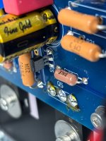
Looking at your picture of the board showing R15, I see RN60 and 2207J. What is its value? That should be an 1k resistor.
Between the jumper and R15 is the bias pot. If current is flowing through it the voltage should change if the pot resistance changes. Perhaps there is an issue with the pot or with the soldering of the pot.
Looking at your picture of the board showing R15, I see RN60 and 2207J. What is its value? That should be an 1k resistor.
Hello Folks, busy with work and cannot get to my bench. But in the mean time I wanted to understand the circuit better so I can better debug (plus it's fun). I did some back of the napkin math, but I haven't used a BJT in almost 20 years so I hope someone can check my math here and see if I am way off. I am mostly unsure of the base voltage of Q4

I think your numbers look reasonable.
The R27 pot controls the Vbe of the transistor and its current, which sets the Vgs of the mosfet through the voltage drop across resistors R25 and R26.
If your amp is not responding to adjustments of the R27 pot, then there is something not right in the circuit comprising R25, R26, R27 pot, Q4, and R15. It is just a matter of determining whether the problem is a faulty component, incorrect component value, faulty connection (solder joint), incorrect component placement, etc.
I agree, After spending some time understanding the circuit the logic place to look is why I am not getting enough drop across the resistors loading q4.I think your numbers look reasonable.
The R27 pot controls the Vbe of the transistor and its current, which sets the Vgs of the mosfet through the voltage drop across resistors R25 and R26.
If your amp is not responding to adjustments of the R27 pot, then there is something not right in the circuit comprising R25, R26, R27 pot, Q4, and R15. It is just a matter of determining whether the problem is a faulty component, incorrect component value, faulty connection (solder joint), incorrect component placement, etc.
I am analog integrated circuit designer, who has been spoiled by simulators doing the math. It was fun to go back to the basics. I am the middle of a tape out so don’t have energy to deep dive this amp, but I have hope I’ll find it soon.
@DominicD - similar to ZM's suggestion of removing parts not in the circuit, perhaps model it with Q4 E to B shorted and see if the model follows what you observe, even if it only solves one channel.
If I short Q4 base and emitter my math seems like its pulling 3mA through R26 .... which is what I measured. What situations would cause the base and emitter to short ?
Yes, a short on the board will do it. If base and emitter are shorted, Vbe=0V and the device is off, and not conducting current.
Simulations are very helpful but the actual physical circuit/board needs to be examined and evaluated. As previously mentioned, there may be other causes for your problem.
Simulations are very helpful but the actual physical circuit/board needs to be examined and evaluated. As previously mentioned, there may be other causes for your problem.
Yeah I am focused around Q4, ill fire up the amp and grab some voltages next. Problem is its drawing alot more current than I want and I worry I will damage it if i just leave it running while I debug.
Well, darn. That may have made life a little easier. The good news is that once you get back to the bench, you can validate your math / sim at various nodes. As Ben notes, that should point you toward the culprit.I think that is just an optical illusion, here is a better photo of q4
Good luck!
Hahah you have no idea, for the run to my bench to look I was super excited you guys found it so easy. I'll do some diode checks with my DMM this weekend.
You can do some trouble shooting without powering it up.
But to get back to Q4, if Q4 was not conducting, the 3 to 4mA measured would go through R25, R6, R27 pot, and R15. And adjusting the R27 pot would affect the total resistance of the resistor string and affect the current and voltage drop across the fixed value resistors.. However you stated that when you adjusted the pot, the voltage did not change.
So a close look at those components should be done. Are the resistor values correct? Is the pot working properly? Are there any soldering problems?

- Home
- Amplifiers
- Pass Labs
- Aleph J illustrated build guide