Hello,
Can someone post the PDF of the Firstwatt documentation. Unfortunately the original link is no longer available:
https://www.firstwatt.com/pdf/prod_aj_man.pdf
Thanks!
BR Barossi
Can someone post the PDF of the Firstwatt documentation. Unfortunately the original link is no longer available:
https://www.firstwatt.com/pdf/prod_aj_man.pdf
Thanks!
BR Barossi

Can you please write something about the performance specifications of the individual pass amps?
Aleph J
F5
F5m
THANKS
Aleph J
F5
F5m
THANKS
You can find the production amp info here: https://www.firstwatt.com/products/
For the F5m, see the docs from Papa's post: https://www.diyaudio.com/community/threads/f5m-kit.408290/
For the F5m, see the docs from Papa's post: https://www.diyaudio.com/community/threads/f5m-kit.408290/
It is TS250VA. I will do few test coming weekend and report.What is the model number of the toroids you used?
Hmmm, you used 2 of these, right? One toroid per each AMP PCB? If yes, you will not need that much capacitance... I know it's a pain to remove the capacitors right after the bridge rectifiers... but that should fix the problem, keeping in mind the type of transformer you chose...
Next time, go for a higher-spec transformer(s)... the supreme range is good... expensive but good (TS400VA SUPREME, 2 x 20V) - zero issues.
Next time, go for a higher-spec transformer(s)... the supreme range is good... expensive but good (TS400VA SUPREME, 2 x 20V) - zero issues.
Folks I am halfway through my build. I have a 25-0-25 300va Toroid that i want to use, but i know this may provide a higher voltage than what is required. I have used 8 15000uf 35V in the DIYAUDIO Universal PSU so here are my questions.
1. With the CRC type PSU, what would be the final voltage - is that ok to supply close to 35v to the amp.
2. My capacitors are 35v, will that be a problem ?
3. Any other ways i can workaround this without changing the toroid ?
Any help is very much appreciated.
Thanks
1. With the CRC type PSU, what would be the final voltage - is that ok to supply close to 35v to the amp.
2. My capacitors are 35v, will that be a problem ?
3. Any other ways i can workaround this without changing the toroid ?
Any help is very much appreciated.
Thanks
1. 25Vac * 1.25= aroundish 31Vdc
2. during startup, which is short, rising to 25Vac*1.4=35Vdc, no biggie
3. change the toroid; or buy another as that o ne, take bigger case and build bigger Aleph
2. during startup, which is short, rising to 25Vac*1.4=35Vdc, no biggie
3. change the toroid; or buy another as that o ne, take bigger case and build bigger Aleph
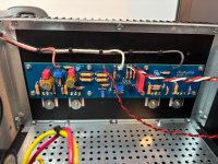
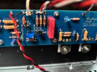
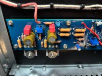
I could use some help. Powering up my Alepha J and the voltage across the emitter resistor is 0.55v. Tested both channels and the emitter voltages are the same, so I must have made the same mistake twice. Things I had checked so far
Thanks for any help, very annoyed with myself right now
- power supply by itself produces good voltages
- desoldered and measure the pots as 1k and 68k
- checked that the right small bjt’s where installed in the proper location
Thanks for any help, very annoyed with myself right now
Attachments

Did it exhibit any questionable behavior with initial power up? Did you use a DBT?
Does turning R27A have an effect on the voltage measured across R18?
FYI - I didn't see anything jump out at me from the pics.
Does turning R27A have an effect on the voltage measured across R18?
FYI - I didn't see anything jump out at me from the pics.
^ I need more clarity re: "and the r18 voltage was lower".
Are you saying that when you turn R27 you can lower the voltage across R18?
If so, then set the voltage to as low as practical (<0V35 preferably). Remove the DBT (if you have not already) and bias the amplifier per the process noted in post #2.
Are you saying that when you turn R27 you can lower the voltage across R18?
If so, then set the voltage to as low as practical (<0V35 preferably). Remove the DBT (if you have not already) and bias the amplifier per the process noted in post #2.
- Home
- Amplifiers
- Pass Labs
- Aleph J illustrated build guide