”Trying to start a Conga line”, almost on Christmas eve, hehe, thats a good one!
🙂👍
🙂👍

You could choose to show the quiescent current per channel. Use the R in the CRC network on the power supply PCB as a perfect place to pick up the voltage drop. Just be aware of one thing: the current will be highish during the warm-up phase and eventually settle to around 85-90% of the initial value (when cold). Furthermore, the readings will be different during winter vs. summer, and again different if you choose to remove the top cover. Do you want (need) to see all those variations on a meter? My suggestion is do not bother.
You could add a proper VU meter, but note that Aleph J has a wonderful frequency spectrum (very wide) with very high input impedance—a perfect, balanced input stage for the rest of the well-catered and nurtured analog system. Any additions you'll need to make in parallel to Aeph J's input will influence the sound. I wouldn't touch it.
You could add a proper VU meter, but note that Aleph J has a wonderful frequency spectrum (very wide) with very high input impedance—a perfect, balanced input stage for the rest of the well-catered and nurtured analog system. Any additions you'll need to make in parallel to Aeph J's input will influence the sound. I wouldn't touch it.
Thanks, @Extreme_Boky. Yeah I'm not going to put anything in the signal path. I'll try to do a bit more reading about quiescent current, see if I can be bothered with it 👍
Do you happen to have any thoughts or advice on the resistors or bridge rectifiers in the other posts? It's gone a bit quiet around this thread and I'm keen to get my BoM order in before xmas 🙂
Do you happen to have any thoughts or advice on the resistors or bridge rectifiers in the other posts? It's gone a bit quiet around this thread and I'm keen to get my BoM order in before xmas 🙂
@RankStranger : The resistors are fine. Being cheap myself I would probably just get a 100 of the Yageo and be done with it. (Note the TE Connectivity one you linked seems to have a min order quantity of 1000.)
For the bridge rectifier, the datasheet you linked is for a whole series. Please check the part number of the ones you have. Anything that is rated over 100V is ok.
For the bridge rectifier, the datasheet you linked is for a whole series. Please check the part number of the ones you have. Anything that is rated over 100V is ok.
Thanks, @Dennis Hui I missed the min qty on the TE and also that the Yageos are 47R, not R47 so 👎
I'll try to cast a wider net, maybe roll the dice on some eBay or amazon ones
Sorry, the part number is the BR354 so Max RMS voltage is 280 and Peak Reverse Voltage is 400. so I'll go with those. Cheers for the assistance 👍
I'll try to cast a wider net, maybe roll the dice on some eBay or amazon ones
Sorry, the part number is the BR354 so Max RMS voltage is 280 and Peak Reverse Voltage is 400. so I'll go with those. Cheers for the assistance 👍
D'Oh! Sorry about the resistance on the Yageo. Reminds me not to answer questions before before 6am and coffee. 🙂
Glad you noticed it.
There should be other choices available without resorting to ebay or amazon...
Edit: Perhaps something like this: https://www.mouser.ca/ProductDetail/KOA-Speer/MOSX3CT631RR47J?qs=OpdMUBmMlYZlrUbH4DzZBg==
Glad you noticed it.
There should be other choices available without resorting to ebay or amazon...
Edit: Perhaps something like this: https://www.mouser.ca/ProductDetail/KOA-Speer/MOSX3CT631RR47J?qs=OpdMUBmMlYZlrUbH4DzZBg==
Last edited:
Ok, ordered. Ended up finding some on DigiKey so I split the order to get free shipping there and mouser 🙂
My christmas is on the 28th when the kids go away with their mum for a week 👍
My christmas is on the 28th when the kids go away with their mum for a week 👍
I’d like to use a 2 pos rotary switch on the front for power.
Is something like this ok? https://www.aliexpress.com/item/1005007796294376.html
Or does it need to be something more sophisticated? https://www.hificollective.co.uk/catalog/lorlin-dpst-rotary-mains-switch-10a.html
Thanks
Is something like this ok? https://www.aliexpress.com/item/1005007796294376.html
Or does it need to be something more sophisticated? https://www.hificollective.co.uk/catalog/lorlin-dpst-rotary-mains-switch-10a.html
Thanks
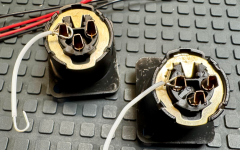
Hi all - using an XLR connector (for the convenience, I know it is not 'better'). For the ground wire, is it OK to run the wire through the little hole for the (cable shield?) or should I keep that isolated? I am not sure exactly what it does or what it is connected to. In one of the build guides, it is NOT connected through this hole. The intent is to ground it with one of the mounting screws to the chassis. If someone feels strongly I should connect to the amp board vs. this way, let me know.
Asking before I solder it.
Thanks!
Asking before I solder it.
Thanks!
Attachments
Also, the discontinued Panasonic ERX-3SJR47 (R16-R23 and R1-R8 in the PSU) don’t appear to be available anywhere I can access them in Australia (at least, without needing to sell some body parts I might yet need).
I've found some matching Vishays (HERE) that are (to me) expensive and some Yageo (HERE) and TE Connectivity (HERE) which are much cheaper. I'm not really familiar with either of those latter brands (although that doesn't mean much, I'm hardly a veteran of this stuff) so I just wanted to check if either of them is a worthy alternative to the Panasonic, if either would be better than the other and, if it is, in fact, a "critical" component that is likely to make an audible difference and I should just stump for the Vishays.
Appreciate any and all advice. Thanks 👍
These resistors are apparently my penance for some terrible thing I did in a past life 🙂
I ordered 25 TE Connectivity ones from DigiKey and they all measure at 0.55 - 0.59 ohms, even though the colour code is correct. DK said they’ll send me some more but that will take time and I had hoped to get most of my build done on my week off.
Are they too far out of spec to use? I need 8 for the PSU and 8 for the amps and I think there’s probably 16 out of the 25 at 0.55 or 0.56. Is it like the caps where X is fine but >X might even be better or is it likely to burn my house down or, worse, the amp won’t sound as good?
Thanks 👍
Just use what you have. The difference, if there is any, will not make much difference in the power supply voltage.
And how did you measure the resistance of the resistors? Low value resistances are difficult to measure accurately with the typical multimeter.
What is the specified tolerance of the resistors? If it is 5 percent, the 0.47R resistors should be between 0.447R and 0.494R.
If you had measured the resistors with a multimeter, you can measure them more accurately by putting them in a circuit in series with a higher value resistor and a power supply. The power supply can be a battery, wall wart, SMPS, lab supply, etc. First measure the resistance of the large higher value resistor. Value of larger value resistor would depend on the power supply voltage and power rating of the resistor. Power up the circuit and measure the voltage drop across each resistor. Use Ohm's Law to determine the current through the higher value resistor. Use the calculated current and the voltage drop across the low value resistor to calculate the resistance. Easy-peasy. 🤓
Thanks, @Ben Mah I measured on an LCR-T4. I did have trouble checking with the DMM but I double-checked the LCR-T4 against some other known values and it seems to be spot on so I’m reasonably confident in the measurement.
I’ll see what DigiKey are proposing but good to know I can use them if I need to. Cheers 👍
I’ll see what DigiKey are proposing but good to know I can use them if I need to. Cheers 👍
Hi all - using an XLR connector (for the convenience, I know it is not 'better').
Well, it probably IS better, but that's not what you're actually asking about...
For the ground wire, is it OK to run the wire through the little hole for the (cable shield?) or should I keep that isolated?
Don't do that.
Connect the little tab thingy to the chassis, preferably with a small wire directly to the screw securing the XLR jack.
Connect pin 1 to signal ground, as this is how the factory F4 are wired.
I am not sure exactly what it does or what it is connected to.
It's a belt & suspenders way to make sure the XLR jack is at the same potential as chassis.
6L6 thanks for the reply, but can you be a little more blunt (like hitting me over the head with a large hammer)? Can you be clear as day where I should connect the 'tab' and where I should connect pin 1? I think I hear you saying:
--Little tab (not any of the three pins, the separate tab thingie) - to the chassis via a short wire like I show...but NOT connected to Pin 1.
--Pin 1 goes to Ground (NOT: negative - ) on the amp board with another wire.
I don't understand the technical reason for this, and would love to learn more.
The difference, if there is any, will not make much difference in the power supply voltage.
I’ve just realised that I need 8 for the PSU and 16 for the amp boards. Will the difference matter for the amplifier circuit? It doesn’t seem like a huge difference but I’m not sure if they have a critical role
I measured on an LCR-T4. I did have trouble checking with the DMM but I double-checked the LCR-T4 against some other known values and it seems to be spot on so I’m reasonably confident in the measurement.
If the LCR-T4 is one of those less than $20 multi-testers, I would not trust it with low value resistance tests. For the amplifier output mosfet source resistors I would not rely on the measured 0.55 to 0.59 Ohm for Iq determination. If the measurement is in error and the resistor is actually 0.47 Ohm, the current would be higher than assumed.
When you double checked your LCR-T4 against known values, were any of the known values 0.47 Ohm?
If you cannot verify your measured value of 0.55 to 0.59 Ohm, you should use the 0.47 Ohm as marked resistor value for the amplifier amplifier biasing.
Last edited:
- Home
- Amplifiers
- Pass Labs
- Aleph J illustrated build guide