I just completed 2 AJ's to run bi-amp on my B&W 803D, driven by an AR LS17 preamp. No detectable noise of anything, dead quiet. What I did:
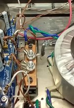
(note picture)
I used twin 18AWG high quality PTFE on every ground connection. The grounding block in the picture uses 3/8 bolts and internal/external tooth locks and the ring connectors are soldered, no crimping. The bolts are torqued to about 35 ft-lbs. Using a calibrated Keithley milliohmeter I measured 28 milliohms from the speaker terminal to the copper of the ground block.
I used only XLR: run the XLR signal ground twisted with IN+, then twist IN- around that to the PCB. Yes, all 3.
EVERY signal ground MUST go to the central point - with the above exception of XLR. Board grounds and speakers. Try to keep ground wires fairly close in length. If you must cross an AC power line, do so orthogonal to the AC as to not couple field current.
Take the XLR static shield to chassis ground.
The Antek transformer I chose specifically for that reason; it has a static shield wire which goes to the central chassis ground.
Take the AC ground to chassis central point as close as possible to signal ground block.
Use an Amtherm 10 ohm varistor from the ground block to the chassis ground.
If you do the above, noise will not be a problem.
Attachments

BTW - compliments to the gang at the DIY store. I purchased a matched quad of 2SJ74, and they all matched within 150uA on my curve tracer. Must be Papa Nelson's magic touch in those ! And thanks to the author of the "illustrated Aleph J build guide", found it very helpful. In fact, a must!
Thank you 6L6, Extreme_Boky. Amazing build guide, by the way!
When I was going through the Rane documents, I missed the part where I needed to remove the loop breaker (NTC thermistor for mine). Thanks for pointing that out!
When I was going through the Rane documents, I missed the part where I needed to remove the loop breaker (NTC thermistor for mine). Thanks for pointing that out!
Thx for your help! It makes wonderful sounds!!!
No buzz. I don't make the HP protect board... I ll try to sell it. Switch on front panel will come.
Thx again!

No buzz. I don't make the HP protect board... I ll try to sell it. Switch on front panel will come.
Thx again!
^ Wonderful!!!!!!!! 🙂 🙂 So happy it all came together. You'll likely modify, improve, and tweak even after you install your front panel switch. For now, if it's quiet and making beautiful music, celebrate your success with some great tunes.
Hello,
I have had my Aleph J up and running for a good year now, and enjoyed it tremendously.
I wanted to change things up and wanted to build a second (almost done - waiting for second enclosure, and backordered parts) , and use them as mono blocks. The only reference close to this I could find is a post from "Dr Greenthumb" in post 9315 where there was a dual mono system. Where I could not get the best handle on the best plan on going about setting up the system to allow for a mono block setup.
Thanks for any input. !!!!!
That post shows fully independent channels (apart from an IEC connector, which is common for both channels).
Are you planning to have two separate chassis? If YES, are you willing to parallel (or bridge) AMP PCBs?? Paralleling (while staying at + and - 24V rails) will give you better drive at low impedances; bridging will possibly give you better drive at high impedances.... but due to the restrictions of the voltage rail potential, you won't achieve much...
I suggest you stick with what's been shown in post 9315... use two separate IEC mains inputs, to prevent a fault in one channel from tripping the power to both channels.... it is also easier to wire the NTCs.. you'll just need two mains cables, but that will clearly show that what you have inside is two completely separate channels of amplification.
I think Modushop has a monoblock chassis specifically designed to accommodate only one AMP PCB, i.e. a chassis with only one heatsink. That can work really well and look very nice.
Thanks for the reply,
Yes, I am going to be doing separate chassis (the second one has just shipped this morning from Modushop -5U 400mm so I can have fun with other builds if need be). I was thinking of doing just that and bridge the PCB's in each chassis to make it "mono" but wanted to confirm if there might be any problems that might arise with doing that.
Cool!!!! I will take my queues from "Dr Greenthumb"s build and bridge the PCB boards within each chassis build.
Thanks.
Hi, still very happy with this amp which works wonderfully. In fact, I built two...one for my brother.
I noticed that one of the two heats up more than the other. With a thermometer I measured 48°C on the radiators for one and 52°C for the other. where can this gap come from? Is this worrying for the hotter of the two? Thank you again for your help!
(4U box)
I noticed that one of the two heats up more than the other. With a thermometer I measured 48°C on the radiators for one and 52°C for the other. where can this gap come from? Is this worrying for the hotter of the two? Thank you again for your help!
(4U box)
Last edited:
Hi Neric, are both amplifiers biased at the same level? Higher bias will definitely cause higher temperature, lower bias will cause the opposite as well. As per the build guide bias should be set at 400mv I believe.
Are both of the cases the same 4U?
Are both of the cases the same 4U?
Another humming/buzzing Aleph... 😅
I have not digested or tried the suggestions I have found in this thread and on this forum yet...
Mine buzzes from the amp itself, even without the speakers attached. As far as troubleshooting goes, I have tried swapping transformers.Both my 20 year old 400VA +/-20 Plitron (more buzz) and new 300VA +/- 18 Antek (less buzz). I cannot feel the vibration by touch. I can't tell if it's a 60 hz, 120 hz or some other frequency buzz. There is no buzz if no amp boards are attached. It buzzes with one amp board is powered. It buzzes more when both channels are powered. So it seems to increase by load to the power supply. This is with no speakers attached! Now if I take this amp to another building, it buzz is less (no speakers) but will increase once it warms up. Dirty mains? I can't tell if the transformer itself is buzzing or if it's the rectifiers. I do have extra rectifiers to try.
From what I can tell, the buzz I hear from the speaker is the same tone as what I hear from just the amp. My phone and spectrum app doesn't seem to be sensitive enough to identify what frequency the buzz is. I can't say for certain if the buzz is 60 or 120 hz. It sounds buzzier than the tones from YouTube.
I will hear a buzz from the speakers even if only one channel is powered. If I move the input wires around. Louder if it's closer to the power wires. Louder if I touch the green ground input wire between the RCA and XLR connectors. The buzz is the same when a source is connected or not and when only one or both channels are connected. At the moment I only have a single-ended source (RCA to 3.5 mm jack to USB-C)
I have braided +in/-in/gnd together to the XLR inlet. Pin 3 at the XLR is shorted to Pin 1 at the plug. Pin 2 and Pin 1 from the XLR are extended to the RCA. I was wondering: Would twisting the +in and -in together cause the noise when using single-ended input even with pin 3 shorted to pin 1?

I think it's a fairlhy vanilla arrangement, although not nearly as tidy as some examples. This is only with one board powered:

The hum appears with or without the speaker protection boars. The chassis ground is separated from ps/signal ground with a CL60. Have confirmed by measuring the resistance between RCA ground and chassis which is ~10 ohms cold.
Bias is currently set at 450 mv. Heatsinks only heat up to around 42-43 ºC. Though another thing I plan on trying is to decrease it to 400 mv, since the buzz from the amp (not speakers) decreases with load.
When only one channel is powered, the buzz coming from the enclosure (not speakers) is less. The buzz coming out of the speakers is the same regardless of one or two channels powered.
I figured I would consult you experience folks before I start unsoldering/messing things up... any suggestions appreciated!
I have not digested or tried the suggestions I have found in this thread and on this forum yet...
Mine buzzes from the amp itself, even without the speakers attached. As far as troubleshooting goes, I have tried swapping transformers.Both my 20 year old 400VA +/-20 Plitron (more buzz) and new 300VA +/- 18 Antek (less buzz). I cannot feel the vibration by touch. I can't tell if it's a 60 hz, 120 hz or some other frequency buzz. There is no buzz if no amp boards are attached. It buzzes with one amp board is powered. It buzzes more when both channels are powered. So it seems to increase by load to the power supply. This is with no speakers attached! Now if I take this amp to another building, it buzz is less (no speakers) but will increase once it warms up. Dirty mains? I can't tell if the transformer itself is buzzing or if it's the rectifiers. I do have extra rectifiers to try.
From what I can tell, the buzz I hear from the speaker is the same tone as what I hear from just the amp. My phone and spectrum app doesn't seem to be sensitive enough to identify what frequency the buzz is. I can't say for certain if the buzz is 60 or 120 hz. It sounds buzzier than the tones from YouTube.
I will hear a buzz from the speakers even if only one channel is powered. If I move the input wires around. Louder if it's closer to the power wires. Louder if I touch the green ground input wire between the RCA and XLR connectors. The buzz is the same when a source is connected or not and when only one or both channels are connected. At the moment I only have a single-ended source (RCA to 3.5 mm jack to USB-C)
I have braided +in/-in/gnd together to the XLR inlet. Pin 3 at the XLR is shorted to Pin 1 at the plug. Pin 2 and Pin 1 from the XLR are extended to the RCA. I was wondering: Would twisting the +in and -in together cause the noise when using single-ended input even with pin 3 shorted to pin 1?
I think it's a fairlhy vanilla arrangement, although not nearly as tidy as some examples. This is only with one board powered:
The hum appears with or without the speaker protection boars. The chassis ground is separated from ps/signal ground with a CL60. Have confirmed by measuring the resistance between RCA ground and chassis which is ~10 ohms cold.
Bias is currently set at 450 mv. Heatsinks only heat up to around 42-43 ºC. Though another thing I plan on trying is to decrease it to 400 mv, since the buzz from the amp (not speakers) decreases with load.
When only one channel is powered, the buzz coming from the enclosure (not speakers) is less. The buzz coming out of the speakers is the same regardless of one or two channels powered.
I figured I would consult you experience folks before I start unsoldering/messing things up... any suggestions appreciated!
Internal wiring inspired by works of Sergio Lione?
"There is no buzz if no amp boards are attached. It buzzes with one amp board is powered. It buzzes more when both channels are powered. So it seems to increase by load to the power supply. This is with no speakers attached! " ... so it ain't DC-on-mains issue
Can't see which wire goes where... you need to segregate wiring... low signal, DC, speakers, mains...
Drop bias to 400mV... that should help.
It seems that you have possible oscillations that might be causing excessive power drain from the toroids... measure the voltage drops across the PS PCB CRC... across Rs, and see what you have there. Then compare to see if the voltage drop across those resistors is the sum of the quiescent current from both AMP PCBs. Or, put an oscilloscope on V + and V - OUT, and check...
The best place for the snubber is as close as possible to the secondary wiring.... hence, you could install the snubbers on the bridge rectifiers... just use dual lugs and re-crimp... or use something like this:

The fact that your speakers are buzzing as well tells me that you need an AMP PCB ground lift mod. Do you really need to keep RCA INs?
"There is no buzz if no amp boards are attached. It buzzes with one amp board is powered. It buzzes more when both channels are powered. So it seems to increase by load to the power supply. This is with no speakers attached! " ... so it ain't DC-on-mains issue
Can't see which wire goes where... you need to segregate wiring... low signal, DC, speakers, mains...
Drop bias to 400mV... that should help.
It seems that you have possible oscillations that might be causing excessive power drain from the toroids... measure the voltage drops across the PS PCB CRC... across Rs, and see what you have there. Then compare to see if the voltage drop across those resistors is the sum of the quiescent current from both AMP PCBs. Or, put an oscilloscope on V + and V - OUT, and check...
The best place for the snubber is as close as possible to the secondary wiring.... hence, you could install the snubbers on the bridge rectifiers... just use dual lugs and re-crimp... or use something like this:
The fact that your speakers are buzzing as well tells me that you need an AMP PCB ground lift mod. Do you really need to keep RCA INs?
Last edited:
Hi,KevinTams -
Sorry I didn't see this earlier.
Input from single ended is -- RCA center to +IN, RCA outer to GND, jumper -IN to GND.
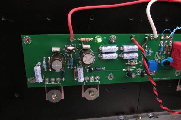
Thats the best photo I have, it's a little small, sorry. But you can see the fine blue wire from -IN to GND, the white fom RCA outer to GND, and Blue, RCA center, to +IN
Where is C1? omitting that is going to cause problems. Are your Jfets still good?
Is the blue wire needed between -IN and GND? ...I didn't put it on.
For your RCA input, yes!
If you still got hum there is a little tweak to apply mentioned frequently.
If you still got hum there is a little tweak to apply mentioned frequently.
If I got no hum without the wire between -IN and GND, should I put it on anyway? I use RCA input only.
What is this jumper for? Are there any risks if it is not installed?
What is this jumper for? Are there any risks if it is not installed?
You should use the jumper between GND and -IN for RCA input. See example here.
Without jumper use XLR- input.
Without jumper use XLR- input.
You need it to get the specified 10x (20dB) gain for RCA input.
^ 
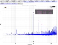
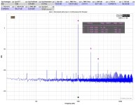
@neric34 - You're certainly not the first to ask this. Here is a super-duper quick demo. I grabbed a board off the shelf, put it on a heatsink and fired that bad boy up to demonstrate. Notice the gain. You can ignore most of the distortion stuff since it was literally just a naked board on a heatsink with a pile of clippy leads running to and fro. 1W output.
It also goes to show that a lot of folks don't need a ton of gain. There have been a few people that say that the Aleph J sounds quite nice without the jumper in place with... 0 gain. 🙂
Edited to add - ignore the file names... I was working on something else and was on a roll with naming convention... brain fade. Main thing is 1W out with jumper on and off.
Attachments
- Home
- Amplifiers
- Pass Labs
- Aleph J illustrated build guide