
nothing wrong with soldering while listening True enough, point I meant to imply is that motivation to build another amp fades.
I'm doing that all the time - practically never one without other and vice versa
in fact, only when I'm in bedroom there is no music - Boss forbade Zen Mod is wise to give the woman of the house her due.
Speaker recommendations: Has anyone paired the Aleph J with KEF R3 Non Meta / B&W 706 S3 / Revel M106 ? I have seen Pass amps paired with larger JBL's and Herseys, but did not find any tests / demos with smaller & newer designs. Any thoughts (and your recommendations) would be helpful.
p.s. I did find an old thread from 2014 on subject but it does not address the pairing options much.
p.s. I did find an old thread from 2014 on subject but it does not address the pairing options much.
Hoping to get some feedback from an AJ builder who has tried connecting and is using XLR input connectors. (I'm using Nuetrik) When wiring:
1 - Do you tie the SHIELD to chassis ground. (assume yes)
2 - Do you tie the GROUND to the star DC ground block, or to the specific assigned ground solder terminal of the PCB signal input?
Thanks!
1 - Do you tie the SHIELD to chassis ground. (assume yes)
2 - Do you tie the GROUND to the star DC ground block, or to the specific assigned ground solder terminal of the PCB signal input?
Thanks!
Great, thanks. The question was on GROUNDS only, but good fill-in. No mention of shield, but tying to chassis ground which makes sense since it's not referenced to anything in the signal domain.
Not clear then on what you were asking. You asked about "XLR input connectors". So I replied with connection of "XLR input connectors". When you mentioned shield, were your referring to the shield pin on the XLR, which is also the Ground pin on the XLR?
In your two questions, what are "SHIELD" and "GROUND"?
In your two questions, what are "SHIELD" and "GROUND"?
Nuetrik connectors have POS, NEG, GND. They also have a SHIELD. Wire for XLR has 3 conductors plus shield. Mouser: NC3FD-L-B-1
So the question was really about the signal ground. Again, since every other ground returns to the common start ground point, should the signal input be any different? If you are using XLR, and you connect it's ground as you indicated and no noise issues, then all is well!
So the question was really about the signal ground. Again, since every other ground returns to the common start ground point, should the signal input be any different? If you are using XLR, and you connect it's ground as you indicated and no noise issues, then all is well!
The shield tab is usually connected directly to the chassis ground. But one thing to watch out for is the shield tab on the XLR connector attached to the interconnect cable. If the shield tab on the cable XLR connector is connected to a cable shield and the cable shield is also connected to ground, then there may be a hum problem.
The connector I have is isolated from ground to shield. But an interesting paper. IMO, since XLR is differential signalling it should never tie a shield to ground which would defeat the purpose. Single ended cables like RCA use the wire around the core as ground, which is why ground loops can be a nuisance with single ended.
Thanks for the feedback.
Thanks for the feedback.
Has anyone documented a full procedure on setting all 3 pots on the PCB? For example, what is the starting position of R7, R8 and R27? What is the first adjustment, checking what voltage(s)? And next...
Just found 6L6 posts 384 and 390. Will set the pots and check again. Rail voltages are +/-23V, signal inputs grounded. Problem - could not get DC offset in range. Will try again and report back, thanks.
I adjusted pots R7, R8 = 1K (12 turns) , and R27 to 68K (17 turns). Rail voltage is exactly -22/+22. Signal input is shorted.
Was able to adjust offset to 0 on left channel, and 12mV on right.
Bias R27 isn't adjusting. I could only get to 610mV on right, and 450mV on left. This, after adjusting R27 up a few turns, and down a few turns.
Suggestions?
Was able to adjust offset to 0 on left channel, and 12mV on right.
Bias R27 isn't adjusting. I could only get to 610mV on right, and 450mV on left. This, after adjusting R27 up a few turns, and down a few turns.
Suggestions?
Last edited:
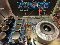
Did a bit more testing. Following the "build guide", I tried to adjusted R27 BIAS first, but it doesn't move from about 600mV. I also checked orientation and type of Q2 (BC560C) and Q3,Q4 (BC550C). These were new devices. It seems suspicious that the problem is the same on both channels (bias not adjusting) but the left is a bit lower at 460mV. Picture of chassis attached.
Attachments
Working! Didn't have jumper R27 in place. After installing, let it warm up for 20 minutes or so, then was able to get bias in range. All good.
I am about to wire mine and I am still a bit undecided as to which way to wire it.Alternate Input Wiring for Reduced Hum and Noise
When I finished by Aleph J back in May, I intended to use it only in single-ended mode so I wired it according to the build guide. While I achieved 70-80 microVolts of hum/noise with inputs shorted, I had 100-200 microVolts when connected to my B1, B1 Korg preamps or directly to my Bel Canto DAC3. Not terrible, but not within factory spec of the commercial version. After some though, I decided to wire it up the inputs as balanced and found mbrenna's post, #4971, where he referenced a great document by Rane Commercial about grounding protocol.
So, following mbrenna's and Rane's recommendation, I came to the following wiring scheme which gave me 70-80 microVolts of hum/noise with inputs shorted and with preamps/DACs connected:
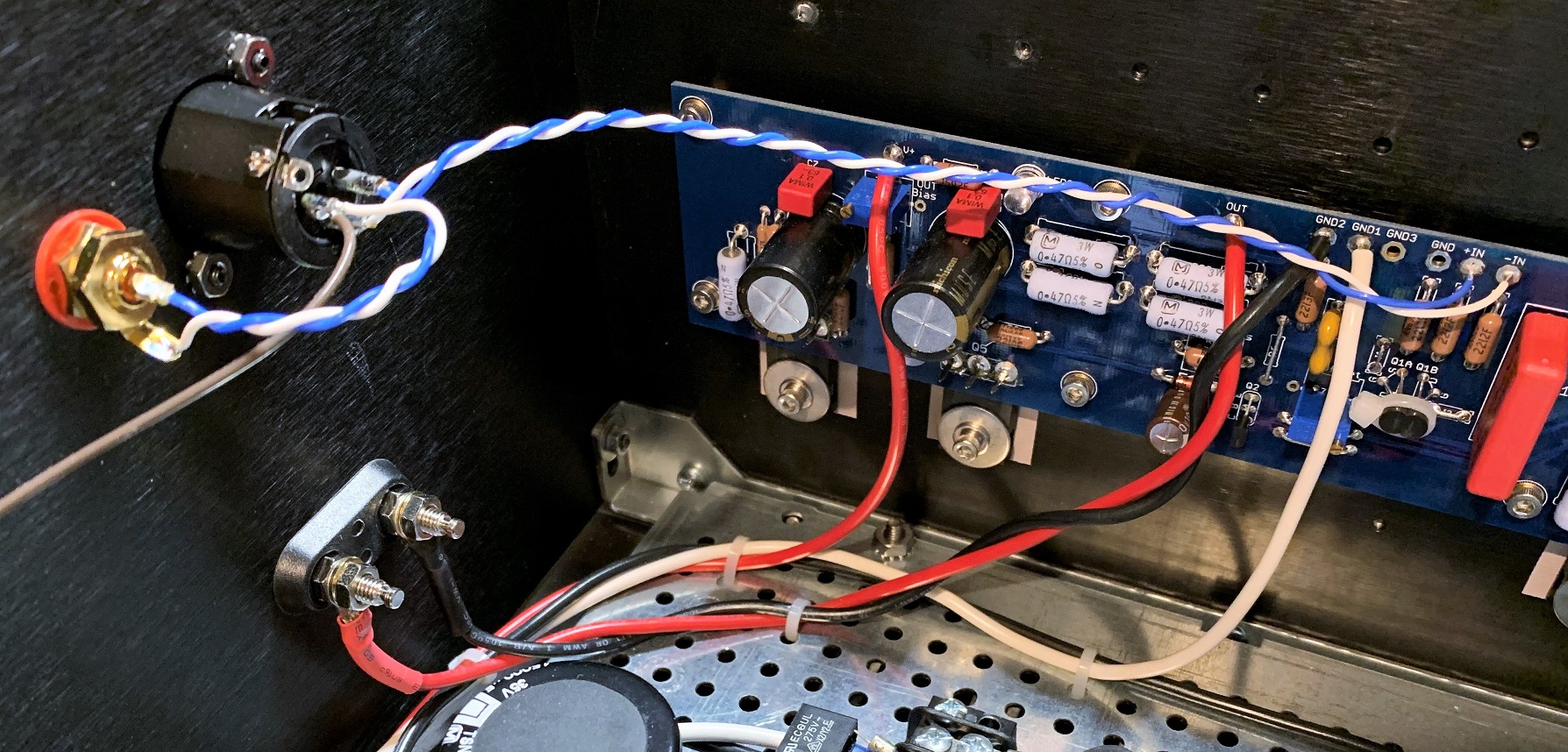
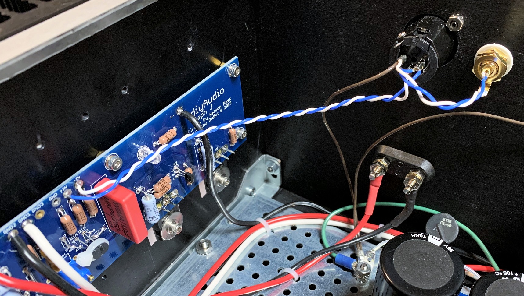
Key is to run a twisted pair of the plus and minus signal to the inputs and ground the XLR ground or single ended ground at the cable entrance. See the Rane document for more info. Now I have a very quiet amp and did not have to resort to cutting traces as some have done to reduce hum.
In your example, XLR pin 1 is attached earth/chassis which is consistent with the Rane document. What is the rationale for connecting the unbalanced ground to earth/chassis? The Rane document seems to suggest otherwise (output configuration 17), but I may not be interpreting this correctly...
Thoughts/opinions?
You are interpreting it perfectly...
Rane's implementation/suggestion applies to XLR input, and assumes a few things (that exist only in professional audio gear... or FW Clone builds that are being converted as per below):
- Rane's implementation can be tried (and will work well) only if used on the XLR input - the RCA and its associated connecting wiring to the XLR connector, should be removed (they can stay, but it is not easy to make it work correctly from the noise coupling point of view, as Rane intended)
- The NTC between PS PCB common, and the chassis will have to be removed (replaced with a short thick wire)
- The back panel, mains earth, amplifier chassis and the PS PCB & AMP PCB common, have to reside at the same RF / HF potential. Long earth wires, long (and thin) NTC wires, NTC in itself... are a no-no...
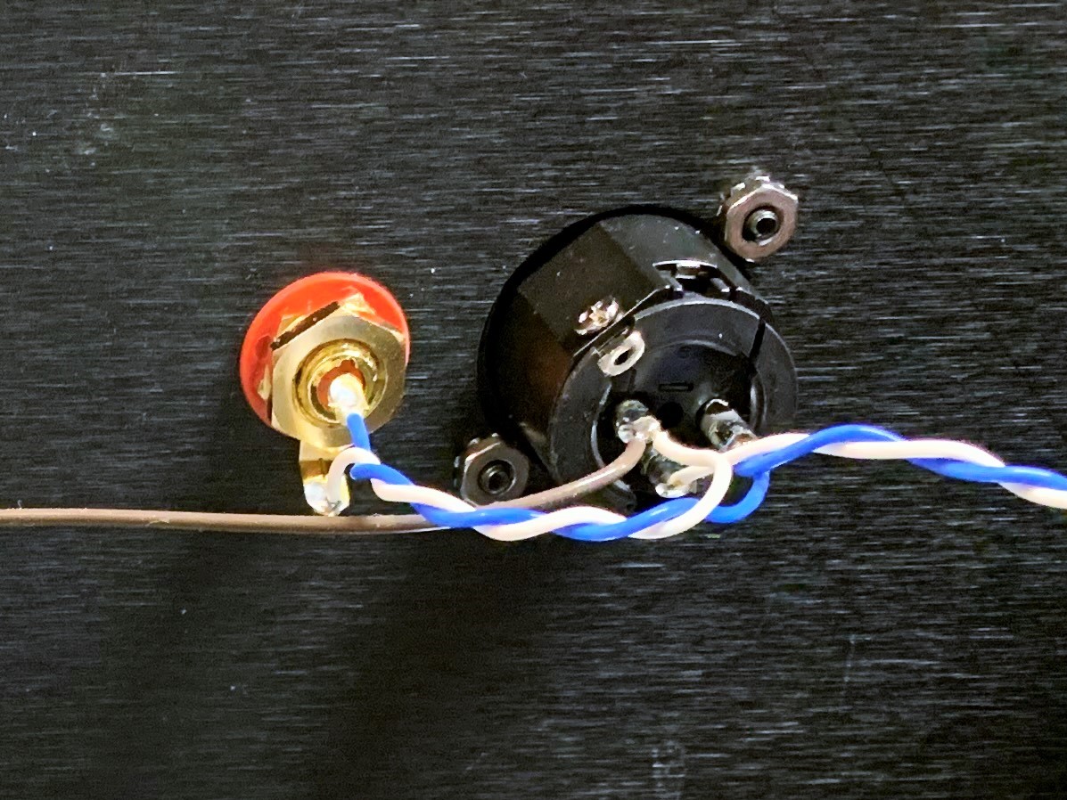
- The XLR pin 1 (shield coming from the source) should be dumped to the amplifier chassis potential (to the XLR connector shell lug) only via a very short wire as shown below in yellow (the black paint should be scraped away, to ensure the XLR shell makes good RF / HF contact with the back panel - with the rest of the amplifier chassis)
Last edited:
- Home
- Amplifiers
- Pass Labs
- Aleph J illustrated build guide