Sounds like you're on a great path. If you have trouble finding the sizes for anything, feel free to ask. The spec sheets for most parts have a technical drawing also.
Andy can confirm, but he may be referring to something like this re: pin connectors.
https://www.amazon.com/gp/product/B07XBLGPCY/ref=ppx_yo_dt_b_asin_title_o04_s00?ie=UTF8&th=1
Enjoy your build.
Andy can confirm, but he may be referring to something like this re: pin connectors.
https://www.amazon.com/gp/product/B07XBLGPCY/ref=ppx_yo_dt_b_asin_title_o04_s00?ie=UTF8&th=1
Enjoy your build.
Same here. Most of those plastic covered ones I grab with needle nose, hold it in flame and scrape the plastic off. Solder, cover with shrink wrap.I highly regard direct soldering and or shrinked needle pins instead of fastons. Not as flexible, but ensures tight sleep every night
Russellc

I'm curious what a needle-pin is as a connection. Could someone share a picture?
I used a lot of fast-on connections in my builds. Bought lots of crimp-on connectors in various sizes (20awg, 16awg, etc.) from Amazon
I used a lot of fast-on connections in my builds. Bought lots of crimp-on connectors in various sizes (20awg, 16awg, etc.) from Amazon
I'm curious what a needle-pin is as a connection. Could someone share a picture?
I used a lot of fast-on connections in my builds. Bought lots of crimp-on connectors in various sizes (20awg, 16awg, etc.) from Amazon
Attachments
Thank you.
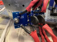
looks like some are soldered fast-ons and some are wires soldered into the board.
Do some have a physical pin in them?
looks like some are soldered fast-ons and some are wires soldered into the board.
Do some have a physical pin in them?

Thank you.
looks like some are soldered fast-ons and some are wires soldered into the board.
Do some have a physical pin in them?
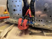
I used a Mogami W3101 4mm² (#12AWG) cable and heavy-duty pure copper Terminals PIN WIRE 16-14AWG (Mouser):
https://au.mouser.com/ProductDetail/TE-Connectivity/165045?qs=HjC056NR38F9ygYZj8ieGw==&countrycode=AU¤cycode=AUD
Check the picture I attached. That 4mm² (#12AWG) wire can almost fit... the remainder can be carefully spread on top of the pins and then soldered. You'll need a 60 - 80W soldering iron.
Yes, it looks that way but is not. I used pins looking like the ones MZM posted, but without isulation. First presoldered the wires, then machanically shrinked the needle pins, then solder it all together with a bunch of flux and a huge solder tip. Then soldered that to the board. So four processes. Not going anywhereThank you.
looks like some are soldered fast-ons and some are wires soldered into the board.
Do some have a physical pin in them?

Presoldered=tinned
Shrinked=crimped
Up in the middle of the night, travel, words lost 🙂
I used copper pins from Mouser, tinned. Can’t remember/find the part nr now.
btw: purely MZM’s recipe.
Shrinked=crimped
Up in the middle of the night, travel, words lost 🙂
I used copper pins from Mouser, tinned. Can’t remember/find the part nr now.
btw: purely MZM’s recipe.
Last edited:
I had all the bits to make an AJ, was waiting for the DIYaudio Store to get some boards in and got bored. So I looked at some layouts, learnt KiCAD and got a few PCB’s made in china. Just finished stuffing my first board and hopefully get the second done tomorrow. I still need to sort out my heatsinks and power supply. Should have magic smoke or an amp in a couple of weeks. Never made an amp from scratch so fingers crossed

Congratulations! If those are your first PCB layouts, you've got quite a talent for this kind of work!!
Thanks Mark. They are unproven and like I said, I looked at few other layouts ( I copied some bits ).

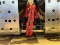
Reminds me La Linea cartoon.
https://www.google.com/search?q=la+...O4CmYQ_AUoAnoECAIQAg&biw=412&bih=718&dpr=2.63
https://www.google.com/search?q=la+...O4CmYQ_AUoAnoECAIQAg&biw=412&bih=718&dpr=2.63
I had all the bits to make an AJ, was waiting for the DIYaudio Store to get some boards in and got bored. So I looked at some layouts, learnt KiCAD and got a few PCB’s made in china. Just finished stuffing my first board and hopefully get the second done tomorrow. I still need to sort out my heatsinks and power supply. Should have magic smoke or an amp in a couple of weeks. Never made an amp from scratch so fingers crossed View attachment 1082788
Sweet!!🙂
I really like the placement of the placement of the +/- 24V solder points. The heart rate monitor is a added bonus cool touch 😎👍
- Home
- Amplifiers
- Pass Labs
- Aleph J illustrated build guide