Brad,
I agree with Ben you need to revisit Q2 - Q4. Check that you have the correct parts and installed in the correct orientation.
Please also measure the voltages across the zener D1 and the resistors/pots R8 and R7.
I agree with Ben you need to revisit Q2 - Q4. Check that you have the correct parts and installed in the correct orientation.
Please also measure the voltages across the zener D1 and the resistors/pots R8 and R7.
I missed ordering the 1K for R8, somehow, but I do have a 1/4 watt 1K-
https://www.mouser.com/ProductDetail/Vishay/CMF501K0000FKR6?qs=4eNa8160l8UxuOjANAiVTQ%3D%3D
For this series the BOM lists the 1/2 watt version, and I did see one post suggesting 1/4 watt might be small for that location. Is the one above okay to use?
https://www.mouser.com/ProductDetail/Vishay/CMF501K0000FKR6?qs=4eNa8160l8UxuOjANAiVTQ%3D%3D
For this series the BOM lists the 1/2 watt version, and I did see one post suggesting 1/4 watt might be small for that location. Is the one above okay to use?
Last edited:
1/4W is fine. You're expecting about 8.5V across R8 so the dissipation is less than 0.08W.
Edit: You were probably thinking of R5, which connects the negative rail to the zener D1. That guy dissipates over 1/4W.
Edit: You were probably thinking of R5, which connects the negative rail to the zener D1. That guy dissipates over 1/4W.
Last edited:
If it was working prior to replacing Q2 - Q4 and stopped working after replacement, then most likely one or more of the replacement parts are faulty.
So at this point you should remove Q2 - Q4 and check to see if they are faulty, and replace if necessary.
Brad,
I agree with Ben you need to revisit Q2 - Q4. Check that you have the correct parts and installed in the correct orientation.
Please also measure the voltages across the zener D1 and the resistors/pots R8 and R7.
Thanks, Ben. That would have been the most logical way to do things. I jumped the gun a bit on moving along to the next set of parts replacements. Per your and Dennis's recommendations, I will check Q2 - Q4 and also let you know the zener and R7/R8 voltages.
A very basic and maybe idiotic suggestion: rebuild the channel, new PCB and all.
Thanks, Andy. If the Q2-Q4 thing doesn't work out, I'm taking your advice and rebuilding the channel.
Good plan. What I mean to say is, if all else fails, at some point it might be best to throw in the towel. That said: Ben, Dennis and ZM are helping you. Not exactly nobodies 🙂 A marvelous opportunity to learn from the very best.
Last edited:
1/4W is fine. You're expecting about 8.5V across R8 so the dissipation is less than 0.08W.
Edit: You were probably thinking of R5, which connects the negative rail to the zener D1. That guy dissipates over 1/4W.
Thanks Dennis. That little guy does not look anywhere near the same league as the RN60s next to it. But good enough!
The RN60s are quite large (as you've noted) and you may find them a tight fit at some locations of the PCB.
Have fun with your build.
Have fun with your build.
Please also measure the voltages across the zener D1 and the resistors/pots R8 and R7.
I think I measured correctly...
Good Channel: R7=4.85v R8=8.54v D1=9.01v
Bad Channel: R7=3.16v R8=8.56v D1=9.01v
Hello all-
Can someone direct me to the BOM rev. D and the schematic for the Aleph J? The links seem to be broken.
Can someone direct me to the BOM rev. D and the schematic for the Aleph J? The links seem to be broken.
You can find the BOM and schematic in the DIY Audio Store under Boards/Power Amps, here: https://diyaudiostore.com/collections/power-amplifier/products/aleph-j?variant=5941228356
Finally able to finish my AJ, after reversing the ZTX orientation, replacing the J74s and replacing D1 it is now singing, will burn it in some more and make final adjustments on the bias and offset. Off the bat it really sounds good, no source its quiet as a mouse.I think I will, stay away from it temporarily till the time I can breath a little and have my second wind.
thanks again for all your help.
I will be back soon enough.
Thanks to the generosity of Mr. Pass and all the overwhelming help for all of the experts here, can't say thanks more than enough!
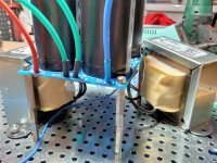
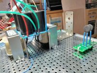
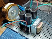
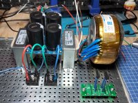
reconsider to move everything to center line, as much is possible (if it is not already made that way)
you'll need space to fiddle with trimpots, and better to eek any possible mm between chokes and amp pcbs
you're good - after dozen or two amps, you'll get it all
🙂
you'll need space to fiddle with trimpots, and better to eek any possible mm between chokes and amp pcbs
you're good - after dozen or two amps, you'll get it all
🙂
I think another transformer and power supply will be installed on the other side, for dual mono. 

I see what you mean now. There is not much space left at the outside edge, so the power supply will be very close to the heatsink and amplifier pcb.
cap bank pcbs can go on slightly higher distancers, then chokes can be tucked in more tightly, then moving them to centerline
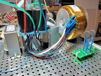
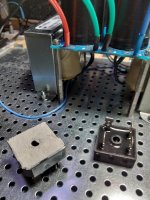
Consider mounting the tranny brackets under the bottom plate. That will give you some extra room to put your bridges right in front of them, instead of on the sides. That will also enable shorter wires from the tranny.Yes, it is dual mono. I'll move everything to the center. Thanks
also, good practice to twist DC wires. Even though Mighty seems to get away with not always doing it. But he uses superspecced custom made trannies, with primary/secondary shielding, and low flux and low loading compared to potential. Maybe that has something to do with it. Or maybe it’s just because he is so Mighty

- Home
- Amplifiers
- Pass Labs
- Aleph J illustrated build guide
