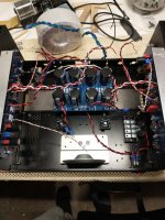
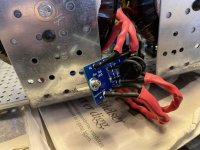
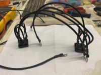
Alright getting close! I apologize in advance for the rat's nest pick and what may be a confusing description. I am about to wire up the power supply and am reconsidering routing options. The power wires are the red, black, and white wires twisted together.
1) Initial thought was to bring them straight out from above the amp boards, then down and alongside the power supply as seen (sort of) on the right hand. My reasoning was max distance from other wires.
2) Another option would be to bring them over the power supply (as sort of seen on the left), which would be a shorter run and not much closer to the input/output wires.
3) Finally, I could rotate the power supply 180 which would be a much shorter run from the caps to the amp boards. I have the power supply on 1" stand-offs, with the AC in wires running underneath. Would probably route the bridge to power supply wires under the power supply unless that should be kept away from the AC in.
Any recommendations?
Attachments
Last edited:
I would choose 2). That seems to keep the wires the maximum distance away from AC.
3) is not a good idea. It's best to keep the wires from the bridge rectifiers to the PS board short.
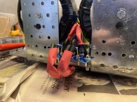
Keeping with the goal of AC away from the amplifier boards, try to locate the two soft start thermistors closer to the transformer and away from the right channel board.
Very important: do not wire everything up and then test the fully complete amplifier. Connect and test in stages, and use a dim bulb tester for each stage's initial power up. So wire up the power supply first and test. If it passes, then connect only one channel and test. If it passes, then connect the other channel and test.
3) is not a good idea. It's best to keep the wires from the bridge rectifiers to the PS board short.
Keeping with the goal of AC away from the amplifier boards, try to locate the two soft start thermistors closer to the transformer and away from the right channel board.
Very important: do not wire everything up and then test the fully complete amplifier. Connect and test in stages, and use a dim bulb tester for each stage's initial power up. So wire up the power supply first and test. If it passes, then connect only one channel and test. If it passes, then connect the other channel and test.
A bit of the last few nights of work. AC section ready sans back plate. Shields ready for connection @ chassis gnd, yet to be established. GLB’s next up, finishing up the PSU section, ready to slide in as planned.
Some pics from work in progress too.
Thanks to Mighty ZM for the soft start boards! Lights no longer blink at power on
Some pics from work in progress too.
Thanks to Mighty ZM for the soft start boards! Lights no longer blink at power on
Attachments
-
 918D3EE8-6705-41F0-8781-488BD7A568B5.jpeg432.9 KB · Views: 163
 -
 8CBF44BD-A7BE-4B9C-944F-C8A990443A3C.jpeg439.5 KB · Views: 162
 -
 6EF5F1E8-F4F5-4B6E-8908-437527F371B4.jpeg370.7 KB · Views: 189
 -
 21B67C33-30EB-4F32-988C-3453E5E80F79.jpeg420.8 KB · Views: 160
 -
 3CA08429-59A0-4F21-94CC-AA24C9A6FE69.jpeg638 KB · Views: 225
 -
 0568051B-F095-462A-BC45-D4701363B0A2.jpeg430.5 KB · Views: 208
A tad overkill, maybeheck of a PS.

OTOH, 0mV measurable ripple @ rails under full load, is promising. Worth it? Dunno. Yet to try 🙂

Crappy Flukes, on their way to OPLDF. Once I get my Tektronix-scope connected I am sure I will find something 
A bit of work on my OCD GLBs last night. Thanks to ZM, Papa and Cubicincher!
chose to solder whatever could be soldered. Attaching some pics in case others with OCD need inspiration.
chose to solder whatever could be soldered. Attaching some pics in case others with OCD need inspiration.
Attachments
Last edited:
A little update on my build...

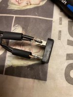
Front panel LED cables

The inner plate is a fantastic option.


Big "third hand" 😀


B side 😀

Stop for today. Ciao!
Front panel LED cables
The inner plate is a fantastic option.
Big "third hand" 😀
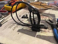
B side 😀
Stop for today. Ciao!
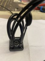
can you avoid that wire routing through holes?
if reaaaaaly unavoidable, at least butcher bigger hole and use grommets
it's so non-Talian looking (OK, let's ignore old Guzzi,Fiat,Lamborgini wiring disasters)
in fact, I simply cringe when I see that
if reaaaaaly unavoidable, at least butcher bigger hole and use grommets
it's so non-Talian looking (OK, let's ignore old Guzzi,Fiat,Lamborgini wiring disasters)
in fact, I simply cringe when I see that
No, I cannot without dismantle everything for makig bigger holes. Pity, I'll put LEDs an GND cables on top
just ensure your AC and high current DC does not pass though those holes. Angles are quite sharp. Wider holes and / or heatshrink / grommets reduce risk.
Then I would not worry. Looks great! Really like the PSU layoutThey are GND and LEDs DC, Andy.
I used only heatsink. Tomorrow I'll search for a solution
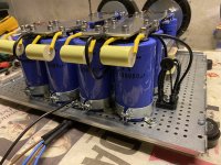
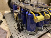
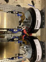
PSU section finally finished. Been posting progress along the way, sorry for all the posts.
Added GLBs and made chassis ground point these last few nights. Seven months in the making, first inside my head, then in practice. my most ambitious project yet. And probably the most foolish and overkill. But just had to try. Excited to find out if it is as quiet as I hope, and worth the effort.
Thanks to all who contributed both with inspiration and help! ZM especially.
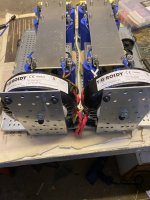
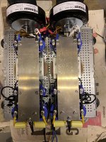
What are we seeing?
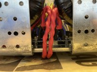
AC under the plate, in huuuuge heatshrink, still inside original AC jacket, for max insulation.
ZM’s NTC softstart board
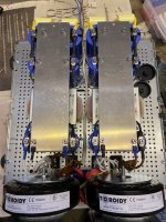
2x Toroidy audio grade transformers @ 300vA @ 18v
4x monolithic bridges
No snubbers, for next project
4 x 47mF, 1 per rail per side
4 x 10mH @ 5A inductors, 1 per rail per side naturally
4 x 47mF, 1 per rail per side
4 x 100mF, 1 per rail per side
For a total of 394mF per rail, split into dual mono meaning 197mF per rail per side.
Ground plane cut by a friend, then hand cut and holes made and plane filed and drilled by yours truly.
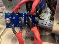
Ground loop breakers from F5 Turbo manual.
Regards,
Andy
Added GLBs and made chassis ground point these last few nights. Seven months in the making, first inside my head, then in practice. my most ambitious project yet. And probably the most foolish and overkill. But just had to try. Excited to find out if it is as quiet as I hope, and worth the effort.
Thanks to all who contributed both with inspiration and help! ZM especially.
What are we seeing?
AC under the plate, in huuuuge heatshrink, still inside original AC jacket, for max insulation.
ZM’s NTC softstart board
2x Toroidy audio grade transformers @ 300vA @ 18v
4x monolithic bridges
No snubbers, for next project
4 x 47mF, 1 per rail per side
4 x 10mH @ 5A inductors, 1 per rail per side naturally
4 x 47mF, 1 per rail per side
4 x 100mF, 1 per rail per side
For a total of 394mF per rail, split into dual mono meaning 197mF per rail per side.
Ground plane cut by a friend, then hand cut and holes made and plane filed and drilled by yours truly.
Ground loop breakers from F5 Turbo manual.
Regards,
Andy
Attachments
- Home
- Amplifiers
- Pass Labs
- Aleph J illustrated build guide