Please post well-lit, in-focus, high-resolution pictures of your left channel board. Maybe we can spot something that is amiss.
Regards, Claas
Regards, Claas
This is not a good time for me, My only phone is in dispose of at the moment, I think I have a few photos while I was assembling the amp previously, not sure how the quality is, will also try to check with a friend if he can let me use his if he's around.
Please post well-lit, in-focus, high-resolution pictures of your left channel board. Maybe we can spot something that is amiss.
Regards, Claas
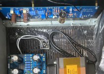
Here are some of the photos, not sure if it will help, I will try to look for a better one.
This was taken when I was trying out the mounting and have not soldered in the Mosfets and cables yet.
Attachments
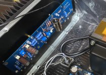
Well, unfortunately I can't see much in those pictures because of the oblique angle.
However, a few things come to mind:
- You can compare resistor values with the good channel
- You do have 2SJ74 in the Q1A and Q1B position ?
- What transistor do you have in the Q2 position, and did you check its pinout ? (If you used the same one in the right channel with the same orientation, its likely correct)
Regards, Claas
Well, unfortunately I can't see much in those pictures because of the oblique angle.
However, a few things come to mind:
- You can compare resistor values with the good channel
- You do have 2SJ74 in the Q1A and Q1B position ?
- What transistor do you have in the Q2 position, and did you check its pinout ? (If you used the same one in the right channel with the same orientation, its likely correct)
Regards, Claas
Hi Chede, thanks for your reply, sorry for that awkward angle.
Yes I used 2SJ47 for Q1A and B, I still have a couple spare but would not risk it.
I used ZTX550 for Q2 and orientation is that the flat side faces towards C1 and the rounded side towards D1.
I am still a quarter of the way in testing and confirming values on all resistors.
Just a question what does Q2 do for Q1A and B?
Q2 is a current source, feeding a bit over 8mA to Q1a and Q1b.
What are you using for R6/R8/R8'?
What are you using for R6/R8/R8'?
Q2 is a current source, feeding a bit over 8mA to Q1a and Q1b.
What are you using for R6/R8/R8'?
R6 says 562K I have not pulled it out yet to test and confirm, for r8 is a 500R bourns trimmer.
Last edited:
Hmm ... if R6 is truly 562k, than the problem might originate here.
Do you have 562k in the other, working channel as well ?
Schematic in post #1 says "Jumper" for R6. If R6 is 562k, I would expect that base-emitter voltage of Q2 would go to about 15V immediately upon switch-on. Data sheet for ZTX550 says max allowed base-emitter voltage is 5V ... So, if Q2 then fails from overvoltage, I guess we have undefined conditions at the JFETs ...
Regards, Claas
Oh my! Thank you for pointing out my mistake, 562K is totally over the required resistor after looking at the schematics again.
I will check if if still have spare 560R or better yet just use a jumper, in any case I will double check again other resistors on the board and compare them again with the schematics.
Big mistake on my part.
Will also check if I still have ZTX550. Hope those are the only ones that got defective.
Will update soonest as I get my hands on the boards again.
Last edited:
Hi Chede, thanks for your reply, sorry for that awkward angle.
Yes I used 2SJ47 for Q1A and B, I still have a couple spare but would not risk it.
I used ZTX550 for Q2 and orientation is that the flat side faces towards C1 and the rounded side towards D1.
I am still a quarter of the way in testing and confirming values on all resistors.
Just a question what does Q2 do for Q1A and B?
Hi,
I was under the impression that ZTX450 and 550 share polarity and that the flat side should point towards the left, i e the opposit of the way you mounted it:
ztx550 ztx551.pdf PDF datasheet. ALL TRANSISTORS DATASHEET. POWER MOSFET, IGBT, IC, TRIACS DATABASE. Electronic Supply. INNOVATION CATALOG. Service
Thanks for the heads up, this board is in total chaos, I have to most likely redo everything for the left board.
I think I will, stay away from it temporarily till the time I can breath a little and have my second wind.
thanks again for all your help.
I will be back soon enough.
thanks again for all your help.
I will be back soon enough.
Just got hold of a pair of Frugals with Markaudio Alpair 12Ps. Being speakerless, I thought approx 200 dollars was too good a deal to pass on. It is just an impulse temporary solution, having too many projects going to handle. Wonder how they fare with the J Zen… maybe become a stayer? Dreaming of SLOBs, but being a while away, maybe this will surprise me? Mighty: I know this isn’t audiophile retirement, but hey, why retire just yet?
Regards,
Andy
Regards,
Andy


Thanks, guys! Appreciate it. Kinda psyched, never tried a full range and or crossoverless driver before 🙂
Or horns, for that matter. Much to learn.
Or horns, for that matter. Much to learn.
Last edited:
- Home
- Amplifiers
- Pass Labs
- Aleph J illustrated build guide