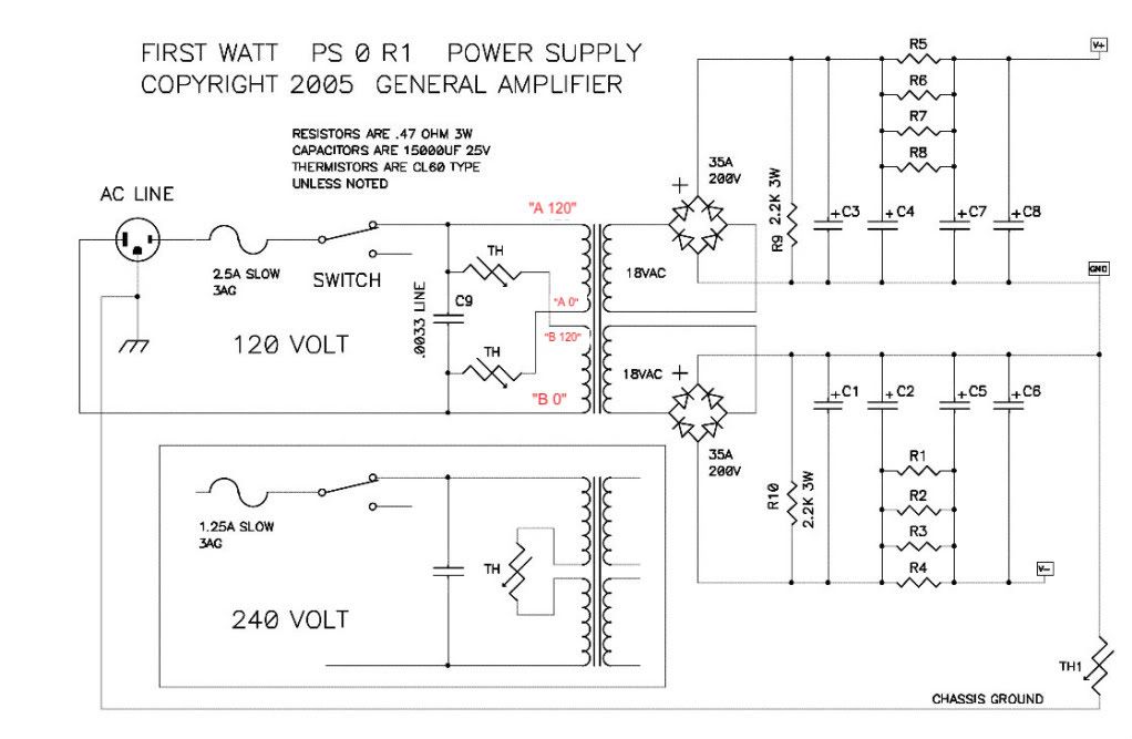
Here is a annotated board that I did a while back(Not my board but a great looking one), Please use with caution as not sure anyone but me has proofed it. I am still working with same problem of populated board and which component is which. Good luck. Lots of good help here. C6 and C7 have no components installed yet in picture. Picture is still useful.
I proofed it.... they are my boards. 🙂
Sure - attached.
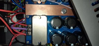
There is still one improvement on the way. I ordered 2 copper bars to thermally bridge the heat sinks. Right now, one is hot and the other one room temperature.
I hope to reduce some temperature a little and increase bias of MOSFETS.
Which chassis did you use for monoblocks?
Transformer problem
Hello all !!
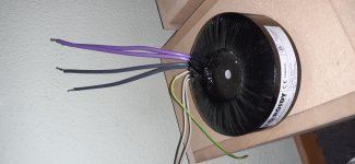
I hope you can help me, I bought a 2 x 18-0-18 v Toroidy transformer audio grade for my aleph J. I really recommend it, is absolutly silent and quiet all performs one step more.
I bought other transformer for build other aleph j for a friend but I have 2 x 18v (4 wires) without gnd.... Is possible use this transformer or I have to bought other new 2 x 18-0-8?? I can connect for find one gnd but I have 36v in the two wires and as you know web need dual centered 18-0-18... not 2x18 😕
I think use ground and chasis like gnd but I think is not correct... thanks for your support....
Hello all !!
I hope you can help me, I bought a 2 x 18-0-18 v Toroidy transformer audio grade for my aleph J. I really recommend it, is absolutly silent and quiet all performs one step more.
I bought other transformer for build other aleph j for a friend but I have 2 x 18v (4 wires) without gnd.... Is possible use this transformer or I have to bought other new 2 x 18-0-8?? I can connect for find one gnd but I have 36v in the two wires and as you know web need dual centered 18-0-18... not 2x18 😕
I think use ground and chasis like gnd but I think is not correct... thanks for your support....
Last edited:
Thanks, I'll conect it direct to ground from the wall... maybe I put in the middle a emi filter.
Thanks again
Thanks again
If I understood well, I have to use between the gnd of PS and gnd of the chassis a Thermistor ? Th1 ?... sorry but I'm not sure, maybe I bought other trafo for my safety.
The 2 x 18-0-18 v Toroidy how many secundary wires has it? 4? 2 times 18v (thick wires) and a thinner (yellow/green?) wire? The yellow/green is connected to an internal shield between primair and secondair. Connect this wire close to the transfo to chassis. This wire is not shown in the schematic above because it is optional. If I understand correctly, the other transfo hasn’t the optional screening, but can be used. (You make ‘gnd’ yourself in the PSU board.)
Hello, I want to say 2x18, 4 wires un total... look the attached picture with the trafo and power supply. The question is that the trafo only has 2x18v and PS need 18-0-18. In this case, I have to find a gnd or change the trafo. Thanks
Attachments
Last edited:
Every Pass/Firstwatt amplifier I've ever built has secondaries in the exact configuration of your Toroidy.
What PSU are you using?
Also, you could combine the middle Purple an Grey wires and the transformer will be 18-0-18.
Also, you could combine the middle Purple an Grey wires and the transformer will be 18-0-18.
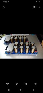
I use the PS you can see in the picture. With ac-gnd-ac input and v+ gnd v- id course for each chanel.
So, i can use the middle grey and purple for get the gnd and get 36v between the other wires, but can i bridge it for the other PS ? or I have to get other trafo ?... sorry but I have a lot of respect with this current level.....
So, i can use the middle grey and purple for get the gnd and get 36v between the other wires, but can i bridge it for the other PS ? or I have to get other trafo ?... sorry but I have a lot of respect with this current level.....
Attachments
Correct, connect the middle gray and purple together. And connect the yellow/green to the chassis. And make the same connections to the second pcb. (3 wires between the 2 pcb’s.)
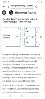
It is possible to connect two identical secondaries to make it a centre tapped secondary.
https://www.electronics-tutorials.ws/transformer/multiple-winding-transformers.html
However, you MUST determine the proper phasing of the secondary windings. If you don't, you have a 50 percent chance of wiring it wrong and destroying your transformer.
You can build a tester to determine the phase:
A little tester to determine transformer PhaseDots with no scope or signal generator
Or if you have a function generator you can use it to determine correct phase. Connect the function generator output to the transformer primary. Connect one secondary wire from each secondary together as a centre tap. Connect a multimeter to the other two free secondary wires. Set the multimeter to VAC. Set the function generator to sine output and a low voltage, such as 1V. Note the multimeter reading. Turn the generator off, disconnect the "centre tap" wires and rewire with one of the secondary wires connected to the other wire of the second secondary. Connect the meter to the free secondary wires and turn on the function generator and measure the VAC.
The correct wiring will have the higher measured VAC from the secondary.
As I mentioned earlier miswiring of the transformer will be disastrous. So you need to be sure that you have identified the correct secondary wires to connect as a centre tap!!
Ok, I see.
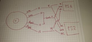
So, with this instructions, I get the schema I attach.
Can I connect in paralel the v+ gnd v- to the two PS ??
Thanks
So, with this instructions, I get the schema I attach.
Can I connect in paralel the v+ gnd v- to the two PS ??
Thanks
Attachments
Last edited:
You don't destroy the transformer when you connect the 2 secondaries in antiphase. They are in series, not parallel. When connected wrong you don't get 36V, but 0 V. No harm done.However, you MUST determine the proper phasing of the secondary windings. If you don't, you have a 50 percent chance of wiring it wrong and destroying your transformer.
Don't look at that circuit, it is very confusing (seems out of context). Transformer is AC not DC as on the shown circuit, you don't have dc at that point.So, with this instructions, I get the schema I attach.
Can I connect in paralel the v+ gnd v- to the two PS ??
(and don't connect the output of the 2 psu's together!)
Sorry, I want to say, when I have the 18-0-18 according schema, Can i connect in paralel the 18-0-18 to the PS input ??
- Home
- Amplifiers
- Pass Labs
- Aleph J illustrated build guide