They are a New Zealand made speaker by a company called image loudspeakers.
The ones I'm grabbing are the image revelations 2
I dont think they will be very well known overseas, but they are a fantastic speaker
The ones I'm grabbing are the image revelations 2
I dont think they will be very well known overseas, but they are a fantastic speaker
Decek,
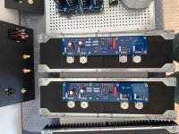
Congratulations on completing your Aleph J mono-block build!
Any pictures you might be able to share? 🙂
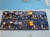
Sure - attached.
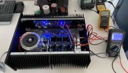
There is still one improvement on the way. I ordered 2 copper bars to thermally bridge the heat sinks. Right now, one is hot and the other one room temperature.
I hope to reduce some temperature a little and increase bias of MOSFETS.
Attachments
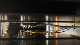
Both sides should be hot. Looking at your power supply board, I do not see any wires linking the two sides of the grounds together at the supply output.
Wires are soldered from the bottom of the PSU board - 4 wires interconnecting both sides.
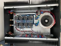
Regarding temperature of the heat sink - this is monoblock. So the Aleph J PCB is mounted on one side only. I hoped that heat would be transferred easily to the other heat sink - in reality heat dissipates on the why the heat sink - mostly on the front and top plate of the chassis.
Any advice how to distribute the heat more evenly?
Cheers
I misunderstood.
There probably isn't a practical way to efficiently send heat across the chassis. On the other hand, the heat sinks on one side are adequate to dissipate the heat anyways.
Oh, I see that you want to increase the bias. It is a shame then that it is difficult to transfer some heat to the other side.
There probably isn't a practical way to efficiently send heat across the chassis. On the other hand, the heat sinks on one side are adequate to dissipate the heat anyways.
Oh, I see that you want to increase the bias. It is a shame then that it is difficult to transfer some heat to the other side.
Last edited:
BenE123,
Googled the brand and the model name, and they look like nice speakers.
Let us know how they sound with the Aleph J.
Decek,
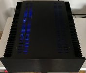
That's a good looking build you have, and very tidy inside. 🙂
Googled the brand and the model name, and they look like nice speakers.
Let us know how they sound with the Aleph J.
Decek,
That's a good looking build you have, and very tidy inside. 🙂
Last edited:
Thanks!
I have one more concern you might help me with.
A new idea for a new project - the balanced version of Korg B1 Nutube.
As reported by other users, it sounds very nicely with Aleph J.
I am considering to buy this volume control and output/input switch from China:
Assembled HiFi 128 Steps Remote Volume Control Board Balanced Preamp Board Relay Pure Resistor|Amplifier| - AliExpress
It is a perfect fit to this chassis:
Hifi Preamplifier Chassis Amplifier Case GOLOMUND Enclosure 430*95*340MM For Remote Control Board|Shell & Body Parts| - AliExpress
What do you think about this volume control and output/input switch?
I can spend extra money on better set - any recommendations?
Like always big thanks in advance
go for it, you can't build it for that money, just in parts alone
no reason to doubt execution, those are straightforward things
no reason to doubt execution, those are straightforward things
Zman01,
Yeah ill post an update when ive tried them out. Ive tried and currently use a set of the image 410's which sound incredible in my opinion. So im hoping these revelations 2 will be quite the upgrade.
Thankyou, now i just have to move onto the next amp project :O
Yeah ill post an update when ive tried them out. Ive tried and currently use a set of the image 410's which sound incredible in my opinion. So im hoping these revelations 2 will be quite the upgrade.
Thankyou, now i just have to move onto the next amp project :O
Thankyou, now i just have to move onto the next amp project :O
It's difficult to stop at one... 😀
Hi Guy's,
I have a question about the temperature and de bias setting for the aleph J. I've build the aleph J a couple of years ago and started at a bias of 400mv slowely over the years I've pushed this to 490mv and the heatsinks are still holding well. I can easliy hold my hand on the heatsinks even on the inside right next to one of the mosfets.
Because i sometimes want to push the volume a bit louder i was wondering how far can i push the bias?
btw my heatsinks are 250mmx400mmx50mm.
Last edited:
Wires are soldered from the bottom of the PSU board - 4 wires interconnecting both sides.
Regarding temperature of the heat sink - this is monoblock. So the Aleph J PCB is mounted on one side only. I hoped that heat would be transferred easily to the other heat sink - in reality heat dissipates on the why the heat sink - mostly on the front and top plate of the chassis.
Any advice how to distribute the heat more evenly?
Cheers
I build a F5 with transistors on opposing heatsinks. I simply ran jumpers from the board to the transistors. You must place.the Gate stopper resistors on the gate pin of the transistors.
Attachments
I run a 470 - 480 mV bias across each resistor. However, instead of just pushing the bias up (which may benefit 4-ohm speakers, which is what I have), see this post (generg, #5744), and then read the next few pages.
https://www.diyaudio.com/forums/pass-labs/241729-aleph-illustrated-build-guide-575.html#post6426914
It seems that the bias setting, together with CCS gain, resistor values/symmetry and DC rail voltages, influences the harmonics' spectra in a way that you may (or may not...) prefer.
https://www.diyaudio.com/forums/pass-labs/241729-aleph-illustrated-build-guide-575.html#post6426914
It seems that the bias setting, together with CCS gain, resistor values/symmetry and DC rail voltages, influences the harmonics' spectra in a way that you may (or may not...) prefer.
.Because i sometimes want to push the volume a bit louder i was wondering how far can i push the bias?
The "bias" control of the Aleph J is actually the AC current gain of the Constant Current Source. It does have an effect on bias, but in this case more is not necessarily better, since you are changing how the current source reacts to the signal. Making large adjustments will change the sound of the amp.
It might sound better, but that's for you to decide.
Thanks for the reply's Extreme_Boky and 6L6. I did hear a slight change in sound in fact. i'l fiddle around with it.
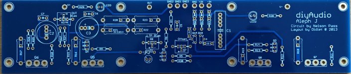
Clear, high resolution photo of empty pcb?
I've just completed building an Aleph J and one amp board is misbehaving. I'm attempting to diagnose the problem by comparing voltages between the good and bad boards, working from the input point, using the schematic. Unfortunately I'm having trouble identifying all the resistors on the populated boards, without access to a clear photo or similar image of the empty pcb. Can anyone point me to such an image? I've looked at the images included in the build guides but either they are already at least partly stuffed, or the image is not of sufficient resolution to read the details on the pcb.
If I continue to hit a wall diagnosing the problem I'll humbly post details and photos, and request a bit of your valuable time and expertise. Before bothering you folks I'll see if I can track it down on my own.
Thanks.
Here's the photo.
Check the posts #5766 and #5767. They contain all information (crucial voltage readings) you'll need to fault-find the amplifier:
https://www.diyaudio.com/forums/pass-labs/241729-aleph-illustrated-build-guide-577.html#post6428705
Check the posts #5766 and #5767. They contain all information (crucial voltage readings) you'll need to fault-find the amplifier:
https://www.diyaudio.com/forums/pass-labs/241729-aleph-illustrated-build-guide-577.html#post6428705
Attachments
Last edited:
Here is a annotated board that I did a while back(Not my board but a great looking one), Please use with caution as not sure anyone but me has proofed it. I am still working with same problem of populated board and which component is which. Good luck. Lots of good help here. C6 and C7 have no components installed yet in picture. Picture is still useful.
Attachments
- Home
- Amplifiers
- Pass Labs
- Aleph J illustrated build guide