Thank you for your fast response, I'm very happy.
I hope the same for my near future F5.
Thanks again.
I hope the same for my near future F5.
Thanks again.
though, it'll sound better with B1 instead, or any properly buffered pot
in which case you can freely use 25 or 50K pot, easier on sources, while pot output is buffered, so no losses from that side
in which case you can freely use 25 or 50K pot, easier on sources, while pot output is buffered, so no losses from that side
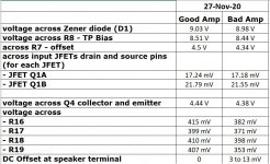
Your left channel behaves exactly as it should (as designed). So, you have a good channel to use as a reference. All you have to do is to compare the voltages between tow AMP PCB's.
Compare the following:
- voltage across Zener diode
- voltage across R8
- across R7
- across input JFETs drain and source pins (for each JFET)
.... then mover to CCS, and measure:
- voltage across Q4 collector and emitter
- voltage across R16, R17, R18 and R19
You may have damaged the input JFETs... use the electrostatic wrist band, and connect it to ground when working with JFETs. Once the JFETs are soldered to the PCB, the wrist band is not required any more.
NOTE: To perform the above measurements, make sure that you have proper probes and do not short anything (maybe have few shots first to calm yourself down🙂; I recommend apricot or pear brandy, but the plum brandy will work just as well...)
Also, write the readings down (have two columns: Good AMP | Bad AMP), and then take a photo and post it here.
Good luck!
Nick
Here are the readings. Those for the JFETs were certainly challenging to get.
Attachments
Great job.
The voltages look good, so the DC stability is fine.
The fact that the sound is distorted AND that the hum/buzz is audible, points to JFETs (in)ability to:
- amplify the input signal
- do power supply CMR of buzz/hum/noise (because one JFET is probably fine; the other slightly damaged => hence, the common mode noise rejection will not work)
So, I'd replace the input JFETs.
Side note: input JFETs can work correctly with regard to DC stability, however, if the gate barrier is slightly damaged (almost always by the static discharge; look at it as a capacitor of very low capacitance - picofarads, that has suddenly developed the ability to conduct a very small amount of DC current, which is a no-no for any capacitor), their ability to amplify will drastically deteriorate.
Few post back I mentioned how important is to use an antistatic wrist wrap (grounded) when handling JFETs. Once soldered on a PCB, they can not be damaged any more.
Regards,
Nick
Last edited:
Sorry when I made confusion.....
the picture with the 0.9A for one pair, resulting in 1.8A for two pairs shows the pos phase
the picture with the 0.65A for one pair resulting in 1.3A for two pairs shows the neg phase
I am sure I am old!
😀😀
"So why is the phase important? Well, it's a subtle thing. I don't suppose everyone can hear it, and fewer particularly care, but from listening tests, we learn that there is a tendency to interpret negative phase 2nd as giving a deeper soundstage and improved localization than otherwise. Positive phase seems to put the instruments and vocals closer and a little more in-your-face with enhanced detail.
Your results may vary, but when I first explored this with the SIT-1 amplifier at First Watt, I had a knob on the front of the amplifier which varied the amount and phase of the 2nd harmonic. It was easy enough to lend the amplifiers to listeners who didn't know what the knob did and gather their comments. Roughly speaking, they tended to prefer about 1% negative phase 2nd harmonic, so it became my standard setting for that knob."
The Pass H2 Harmonic Generator
09-25-2018 | By Nelson Pass | Issue 99
I thought it would be useful to have an explanation of what H2 positive phase and H2 negative phase do to the sound, together with your findings that give the bias values, so people could try "both extremes" (0.9A and 0.65A)
I am running my Aleph J at exactly 1A for one pair... but as soon as I get some free time again, I will play with different bias settings because I do like the idea of having predominant H2 negative phase.
Exactly!
:--))
Again my current values and phase results are from Spice. The real AJ circuit may have different switching points.
For me was especially interesting that more current is not always welcome.
Maybe this vanishing of the neg phase is the reason when Nelson sometimes writes that the special sound of FW amps can be gone when trying to get more power out of them.
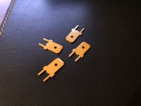
Could someone tell me the part # for the blade connectors please. I back to this build once again. thanks
There are a bunch, but these should work. You can even buy a reel of similar parts and cut them yourself if you need them in bulk and want to save a bit per part.
62409-1 TE Connectivity | Mouser
62409-1 TE Connectivity | Mouser
It should be possible to get rid of the hum. My Alephs are dead quiet. I can't tell if they are turned on with my ears in the cone.
Same with my Aleph J.
^^slick. Last of the small pieces ordered. Led's, thermistors, diodes, etc. Now I just need to keep from getting electrocuted.
Great job.
The voltages look good, so the DC stability is fine.
The fact that the sound is distorted AND that the hum/buzz is audible, points to JFETs (in)ability to:
- amplify the input signal
- do power supply CMR of buzz/hum/noise (because one JFET is probably fine; the other slightly damaged => hence, the common mode noise rejection will not work)
So, I'd replace the input JFETs.
Side note: input JFETs can work correctly with regard to DC stability, however, if the gate barrier is slightly damaged (almost always by the static discharge; look at it as a capacitor of very low capacitance - picofarads, that has suddenly developed the ability to conduct a very small amount of DC current, which is a no-no for any capacitor), their ability to amplify will drastically deteriorate.
Few post back I mentioned how important is to use an antistatic wrist wrap (grounded) when handling JFETs. Once soldered on a PCB, they can not be damaged any more.
Regards,
Nick
Extreme_Boky, thank you very much for the detailed analysis and explanation. Very helpful. I will replace the JFETs and keep you posted.
This is the first transistor amps I have ever built. Are there any documentation somewhere that explains the signal flow and the various components of the Aleph amplifier?
I'd read the "Douglas Self - Audio Power Amplifier Handbook" to start with.
Next step: Nelson Pass white paper publications from:
Pass LabsTechnical Articles - Pass Labs...
....and most definitely the articles published here:
PassDiy
Next step: Nelson Pass white paper publications from:
Pass LabsTechnical Articles - Pass Labs...
....and most definitely the articles published here:
PassDiy
Could someone tell me what's a ballpark cost figure for this build. I have an interested friend,
When it’s all done, ~$700-$900. And that’s buying everything you can to make it easier, deluxe chassis, Back panel kit, parts kits, etc...
You can get it done for less cash outlay if you can do some legwork yourself, but the time and work involved quadruples.
You can get it done for less cash outlay if you can do some legwork yourself, but the time and work involved quadruples.
Last edited:
- Home
- Amplifiers
- Pass Labs
- Aleph J illustrated build guide