Did you do this? (Stolen from 6L6 guide to this PSU board)
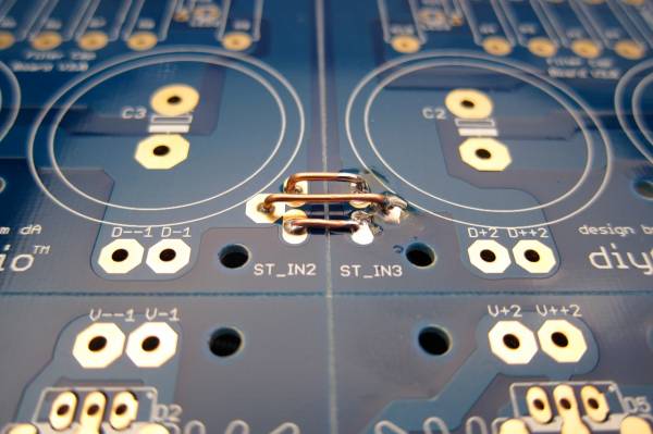
Perhaps they are on the underside? I see several faston tabs, but not clearly see these connections.
Perhaps they are on the underside? I see several faston tabs, but not clearly see these connections.
The AC mains wiring seems to be awfully close to the right channel output. Repositioning it could help with the right channel hum.
Do you have the grounds tied together on each half of the PSU?
Thank you so much for everyone’s help to resolve my amp’s problem. Much appreciated. I would like to recap quickly the initial problem and where we are now.
The amp worked perfectly and sounded great for close to a week with no hum whatsoever. The issue at that time was the turn-on pop and the uncomfortably loud turn-off cracking noise. One morning, I turned on the amp, and it immediately started making this loud 120Hz hum in the right channel. Post #5710.
Thanks to 6L6’s and Zen Mod’s suggestions (post #5736) of moving the RCA ground wires from the chassis to the amp ground and move the XLR out of the picture for now has helped in lowering, but unfortunately not eliminate, the turn on/off pop and crack, especially in the right channel.
The solder joints in the right channel and the power supply have been touched up just in case. The two halves of the power supply board are tied together on the underside. ItsAllInMyHead’s suggestion with repositioning the AC line and right channel output will be worked on later.
These are 2 open questions that confound me now:
1. For the left (good) channel, the initial readings right after power on for the bias is around 425mV, and offset around 15mV. The bias would move DOWN after 20 minutes or so to about 400mV and offset to 4mV. However, the initial readings after power on for the right (bad) channel is around 300mV for bias and 2.4V (2400mV) for offset, and after 20 minutes the bias would move UP to around to 394mv bias, and offset down 12mV. Why the difference in the direction of the bias movements, and very high initial offset voltage? What could cause that to happen?
2. One can faintly hear music played through the right channel, but the sound is very distorted. In the small audio file attached, you can hear the loud hum and the distortion. Does it point to any possibility of component failure? Is there a way to test the JFETs?
What would be the most logical next step?
Attachments
Hope this is the right place, did not find a better one...
😀😀😀
A riddle in pictures to adjust the Aleph J....
Firsts picture:
Aleph J in Spice with 1.8A bias
Second picture:
Aleph J with 1.3A bias
To do it in real, you need to google the software tool "Diana" spectrum analyzer
and of course the a suitable sound card and PC/laptop arrangement.
Have fun adjusting the AJ!
Attachments

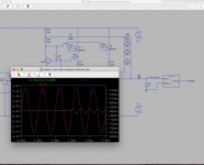
OK, now that's cool. From a "really clean" positive to negative phase H2 with maybe a bit of something else. I'd need an FFT to understand completely. That's accomplished just by changing the bias... At least I think that's what I'm seeing. NEAT!
Also ties into my (poor at this point) attempt to learn Diana in order to see exactly that when I measure amps. More incentive to get off my rump.

Edited for clarity. I really haven't even had a glass of wine yet.
Also ties into my (poor at this point) attempt to learn Diana in order to see exactly that when I measure amps. More incentive to get off my rump.
Edited for clarity. I really haven't even had a glass of wine yet.
Also, the top and bottom panels seems to have a front and back. If holes don't fit, turn it 180deg.
Yup, all my top plates have been "directional" as well. Holes only line up one way.
Russellc
Geneng: That is really cool! Thanks for sharing that. I'll have to see my old HP distortion meter still works...
Nah...just not enough yet. 😀😀😀
I really haven't even had a glass of wine yet.
Nah...just not enough yet. 😀😀😀
I put my old Aleph J back in service today (M2x down for updates this long weekend). It still sounds great! A tiny bit of hum though, in my very efficient speakers. The DIY L4 AudioNoteKits EL34 amp was unusable due to its hum.
Was interesting to learn that the M2x monoblocks were quieter than the Aleph, although I put a fair amount of thought to avoiding hum with M2x, and not much with the Aleph. My old speakers had just a minimal hum with ear up to the cone with the Aleph, that I did not worry about.
Was interesting to learn that the M2x monoblocks were quieter than the Aleph, although I put a fair amount of thought to avoiding hum with M2x, and not much with the Aleph. My old speakers had just a minimal hum with ear up to the cone with the Aleph, that I did not worry about.
It should be possible to get rid of the hum. My Alephs are dead quiet. I can't tell if they are turned on with my ears in the cone.
The bias values shown are of course only for one pair!
:--))
I always get confused when talking Aleph J bias current... hence the following question:
Are you saying that the voltage drop across EACH of the .47ohm / 3W resistors (R16, R17, R18 and R19) is 0.846V? That would give a (single) MOSFET dissipation of 41.67W (!) with the rail voltages of + and - 24V loaded. Still okay I suppose, with a 5U Deluxe chassis.
If the answer is YES, then I think this is very close to how the original Aleph J was shipped out of the factory. I adjusted my trim pots to be exactly the same value as Nelson's original schematics (i.e. R8 was adjusted to exactly 1K, so was the R7), and when I powered my Alepj J for the first time, I measured close to 0.7V drop across each resistor. My rails (loaded) are 24V.
Last edited:
One IRF gets 0.66A x 25V = 16.5W. So I see no problem.
My main intend was to show that more current can change the wanted neg phase.
This is Spice....
Where the point of change is in real ...... Please check it.
:--))
My main intend was to show that more current can change the wanted neg phase.
This is Spice....
Where the point of change is in real ...... Please check it.
:--))
Thank you so much for everyone’s help to resolve my amp’s problem. Much appreciated. I would like to recap quickly the initial problem and where we are now.
The amp worked perfectly and sounded great for close to a week with no hum whatsoever. The issue at that time was the turn-on pop and the uncomfortably loud turn-off cracking noise. One morning, I turned on the amp, and it immediately started making this loud 120Hz hum in the right channel. Post #5710.
Thanks to 6L6’s and Zen Mod’s suggestions (post #5736) of moving the RCA ground wires from the chassis to the amp ground and move the XLR out of the picture for now has helped in lowering, but unfortunately not eliminate, the turn on/off pop and crack, especially in the right channel.
The solder joints in the right channel and the power supply have been touched up just in case. The two halves of the power supply board are tied together on the underside. ItsAllInMyHead’s suggestion with repositioning the AC line and right channel output will be worked on later.
These are 2 open questions that confound me now:
1. For the left (good) channel, the initial readings right after power on for the bias is around 425mV, and offset around 15mV. The bias would move DOWN after 20 minutes or so to about 400mV and offset to 4mV. However, the initial readings after power on for the right (bad) channel is around 300mV for bias and 2.4V (2400mV) for offset, and after 20 minutes the bias would move UP to around to 394mv bias, and offset down 12mV. Why the difference in the direction of the bias movements, and very high initial offset voltage? What could cause that to happen?
2. One can faintly hear music played through the right channel, but the sound is very distorted. In the small audio file attached, you can hear the loud hum and the distortion. Does it point to any possibility of component failure? Is there a way to test the JFETs?
What would be the most logical next step?
Your left channel behaves exactly as it should (as designed). So, you have a good channel to use as a reference. All you have to do is to compare the voltages between tow AMP PCB's.
Compare the following:
- voltage across Zener diode
- voltage across R8
- across R7
- across input JFETs drain and source pins (for each JFET)
.... then mover to CCS, and measure:
- voltage across Q4 collector and emitter
- voltage across R16, R17, R18 and R19
You may have damaged the input JFETs... use the electrostatic wrist band, and connect it to ground when working with JFETs. Once the JFETs are soldered to the PCB, the wrist band is not required any more.
NOTE: To perform the above measurements, make sure that you have proper probes and do not short anything (maybe have few shots first to calm yourself down🙂; I recommend apricot or pear brandy, but the plum brandy will work just as well...)
Also, write the readings down (have two columns: Good AMP | Bad AMP), and then take a photo and post it here.
Good luck!
Nick
Hope this is the right place, did not find a better one...
😀😀😀
A riddle in pictures to adjust the Aleph J....
Firsts picture:
Aleph J in Spice with 1.8A bias
Second picture:
Aleph J with 1.3A bias
To do it in real, you need to google the software tool "Diana" spectrum analyzer
and of course the a suitable sound card and PC/laptop arrangement.
Have fun adjusting the AJ!
The bias values shown are of course only for one pair!
:--))
One IRF gets 0.66A x 25V = 16.5W. So I see no problem.
My main intend was to show that more current can change the wanted neg phase.
This is Spice....
Where the point of change is in real ...... Please check it.
:--))
In the initial post, you mentioned 1.8A.
Then you said that this was for a single pair...
..... and now the 0.66A.😕
This is why I tried to move away from stating the bias current values, to stating the voltage drop across {R16, R17} OR {R18, R19}
I think I'm getting old...

Sorry when I made confusion.....
the picture with the 0.9A for one pair, resulting in 1.8A for two pairs shows the pos phase
the picture with the 0.65A for one pair resulting in 1.3A for two pairs shows the neg phase
I am sure I am old!
😀😀
the picture with the 0.9A for one pair, resulting in 1.8A for two pairs shows the pos phase
the picture with the 0.65A for one pair resulting in 1.3A for two pairs shows the neg phase
I am sure I am old!
😀😀
Hello all !!!
After some Weeks burning the Aleph J, I only can say it's the best amp I ever heard when it's on for 6-8 hours by day !!
I'm using the amp with a marantz sa11 s2 and denon cdc 1600, and this Week a friend bring me a passive preamp, a small box with a 50k potentiometer. I heard a very detailed and amazing sound with my test cd's. But, reading about that I'm not sure if I can damage the amp for use a low level signal. I check temperature and a unusual behaviour but I only can say how many detailed sound I discover..... and how happy I am.
Somebody has any experiencia about that ? Is better use 10k potentiometer or B1 buffer ?? What do you recommend for continue enjoying with the sound. Is adictive how it sounds, bass detail, middle and highs....
Thanks
- Home
- Amplifiers
- Pass Labs
- Aleph J illustrated build guide