Thanks.
I took the input stage from the "Aleph 5" schematics.
I was able to get the appropriate values for the RCA input, but I don't understand what I need to do with the XLR input.
Please consider the resistor values as "tentative".
observe changes on input and also caps at Aleph CCS
I didn't run sim , don't need to
when using RCA input , all you need ( and you really need it!) is to ground neg input
Attachments
The two voltage source (XLR and RCA) interact!
One has to run the two simulation independently, with two different schematics, with the other voltage source deleted.
Version "Aleph 3.E.RCA" is topologically equivalent to the original schematics found in the Nelson Pass paper.
Thanks
One has to run the two simulation independently, with two different schematics, with the other voltage source deleted.
Version "Aleph 3.E.RCA" is topologically equivalent to the original schematics found in the Nelson Pass paper.
Thanks
Attachments
Last edited:
you asked for proper schematic and values of input part , and I gave you that
I can't teach you how to simulate , I'm pretty much greenhorn in that too , learning new things only when I need them
if you search a little , you'll find several well laid and functional simulations of Aleph ; any will do , just edit rails and number of outputs and few resistor values and that's it
...........
One has to run the two simulation independently, with two different schematics, with the other voltage source deleted.
🙂
I bet that's completely logical that you never try to drive your car forward and backward , in same moment
pretty much the same thing
Sorry about that, but now I'm even more confused!
You said
If I don't understand it'm my fault, for sure. Otherwise I wouldn't asked for help.
You said
On the other side you previously said
This is the difference among the "E" version and the "F" version.
Thanks
You said
I searched a lot, and it seems that models and simulation is a "nowhere land".If you search a little , you'll find several well laid and functional simulations of Aleph ; any will do , just edit rails and number of outputs and few resistor values and that's it
If I don't understand it'm my fault, for sure. Otherwise I wouldn't asked for help.
You said
And when using an XLR input?when using RCA input , all you need ( and you really need it!) is to ground neg input
On the other side you previously said
So, what I'm tring to understand, is: R7 (or R102, in the Pass schematics) should be there or not?R102 10K
...
in schematic you show us in post #3212 , just ignore (leave unpopulated) R7 position , and suddenly you'll have proper arrangement
This is the difference among the "E" version and the "F" version.
Why bad?that schm will work , but bad
Thanks
I gave you working schematic
for more , best to find comprehensive tutorial about OP-amp , plenty of these online , either as articles or books for download
there you'll find explanation for each resistor on both inputs of OP , what's their role and preferred value
maybe I wasn't careful enough , but now you confused me ....... and I'm not willing to chase you between several schematics , when you're not following what I'm replying
Aleph is an Aleph is an Aleph ........ differences are mostly rail voltage and number of outputs
if you see one having balanced inputs , you can understand how to make any of them having balanced input
when using balanced input - you are using both negative and positive input of amp
when you choose to use unbalanced input , you're putting signal in positive input , while negative input must be grounded , either with shortie bridge put in XLR (pins 1&3 ) or small switch, without need to add or distract any resistor from circuit
what's there to not understand ?
I don't want to discuss (only) the schematics, I want to understand the different topologies. And as far as I know there are only two possibilities, and not several.but now you confused me ....... and I'm not willing to chase you between several schematics
The one proposed with the "J" and the one proposed by the "5":
An externally hosted image should be here but it was not working when we last tested it.
On one side you see the -XLR left (apparently) floating, o the other you see -XLR connected to the ground by a 10k resistor.
Why I don't see any
So it seems not quite true thatsmall switch
Me, I was interested in the "3" because my simulation of the "J" fails with a wild auto-oscillation, while the simulation of the "3" works perfectly. I shall recheck the models: I trust the millions of diy'ers that have built the "J" successfully.Aleph is an Aleph is an Aleph ........ differences are mostly rail voltage and number of outputs
But ... when designing the "3" Nelson Pass forgot (or wanted not) to put the XLR input.
So, why I cannot have the best of both worlds?
An amplifier
- I understand (and working unbelievably well at the simulator)
- having both inputs: XLR and RCA
Last edited:
Look up the Aleph 30; it has both XLR and RCA inputs, like the A-J.
The small switch is for those diy-ers who prefer to not have to stick a jumper
in the XLR socket when using RCA.
The small switch is for those diy-ers who prefer to not have to stick a jumper
in the XLR socket when using RCA.
The -XLR in the AlephJ isn't left floating. Nelson provides a little wire jumper that is inserted into the XLR connector to tie it to ground when the RCA input is used.
Post your .asc of the 'J'. (According to Nelson, the 'J' sounds better than the '5'. Given that I'd spend my time figuring out what's wrong with your 'J' sim rather than adding balanced input to the '5'.)
Post your .asc of the 'J'. (According to Nelson, the 'J' sounds better than the '5'. Given that I'd spend my time figuring out what's wrong with your 'J' sim rather than adding balanced input to the '5'.)
Look up the Aleph 30 ...
I went searching and thought that I'd found it here:
The Aleph30 PCB layout
but that's a schematic for the Aleph 3.
Eventually found the Aleph 30 manual that has the schematic at the back via this post:
Volksamp Aleph 30 schematic and parts list needed
(attached the pdf for convenience)
But (as far as I can make out) there's no switch to opt for XLR/RCA - check a pic of the original article's back plate:
An externally hosted image should be here but it was not working when we last tested it.
Attachments
Last edited:
But (as far as I can make out) there's no switch to opt for XLR/RCA
That is correct; some diyers added a switch in their builds to avoid the use
of the jumpers between GND and IN- in the XLR sockets when using the RCA
inputs.
Productions units had no switch for the RCA/XLR.
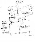
I have a really stupid question.
I am trying to match my IRFP240s. I have calculated that with a 24V supply that I will need a 25 Ohm resistor for the correct current.
So, while I wait for the 24V PSU that I ordered, I used a normal 12V PC PSU to check things out. I am seeing a Vgs of around 7.8V. I was not expecting it to be so high, and I am dropping 4V over the 25 Ohm resistor which gives my about 160mA.
What is going on here?
BTW, I have mounted the MOSFET on a heatsink, but it is not even getting slightly hot.
Last edited:
Can you show how you are hooking things up/schematics used for your measurement?
Maybe someone will spot something.
Maybe someone will spot something.
I had a similar issue using an 18" 22AWG wire with clips to connect the gate and drain. It went away when I connected the pins right on the device.
Can you show how you are hooking things up/schematics used for your measurement?
Maybe someone will spot something.
I am using the diagram as pictured on the last page of this document: PassDiy
I will check out your way, ZM.
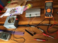
Yes, I am using 22 AWG wire to connect the lot up, as in the attached pic. The resistor is a Caddock MP820.
Attachments
OK, just connected the Gate and Drain on the green connector that connects to the MOSFET, and the problem is gone.
Anybody care to explain WTF is going on? The resistance on the wire causing the issue?
Anybody care to explain WTF is going on? The resistance on the wire causing the issue?
for what Iq you intend to match?
Around 800mA ZM.
(24V - 4V)/0.8A = 25 Ohm.
This was just test run with 12V PSU to see if there were issues, and there was. Monday I get the 24V PSU to do real Iq test. Electronics is funny business sometimes, makes me scratch my head. 😕
Last edited:
- Home
- Amplifiers
- Pass Labs
- Aleph J illustrated build guide