How do you like the sound of the Aleph vs. M2 ? I’m fixing to build either one but can’t decide what direction to go.
Hello again,
When I use the XLR input of the amp I just finished, I get no noise whatsoever with my ear to the drivers of my speakers, which are 99dB efficiency. I just tried the RCA inputs and I am getting noticeable hum. If I don't have any inputs connected, I get hum as soon as I put a shorting bridge between pins 1 and 3 of the XLR input.
I wired the inputs as follows.
XLR pin 1 to pcb ground 2
XLR pin 2 to +in
XLR pin 3 to -in
RCA center to XLR pin 2 (+in)
RCA outer to XLR pin 1 (ground)
- No hum with no inputs connected, but I get hum as soon as I bridge pin 1 and 3 of the XLR.
- A very small amount of hum with no XLR bridge, and RCA input connected, but I don't get full gain.
- Noticeable hum as soon as pin 1 and 3 are bridged with or without RCA connected. Full gain when on RCA.
I am pretty sure my wiring is correct. For wire I used a shielded Belden 8451 microphone cable between the XLR and the circuit board, which has a twisted pair and a stranded drain wire wrapped in a foil shield. +in and -in use the twisted pair, and ground uses the drain wire. I don't have the shield attached anywhere.
Can anyone think of something I've done incorrectly?
Thanks
How do you like the sound of the Aleph vs. M2 ? I’m fixing to build either one but can’t decide what direction to go.
I've only had the Aleph J running for about 4 hours, so I can't really say much of anything useful about it yet, other than it sounds very nice. If you PM me in a week or so I'll give you my impressions, but they probably won't be worth much outside of my system.
I like both very much. If you have the J fet input pieces in hand, build the Aleph J. Definitely build both...one then the other. The M2 is probably the less colored of the two....but Aleph J is really really enjoyable to listen to. Its an amp you will keep coming back to.
Russellc
Russellc
Speaker protection?
Anyone uses a speaker DC protection in the Aleph j? And what do you use? A relay is slow I think. My speakers are quite expensive, and it would be a peace of mind when they are protected.
Anyone uses a speaker DC protection in the Aleph j? And what do you use? A relay is slow I think. My speakers are quite expensive, and it would be a peace of mind when they are protected.
Anyone uses a speaker DC protection in the Aleph j? And what do you use? A relay is slow I think. My speakers are quite expensive, and it would be a peace of mind when they are protected.
A relay is slow? Perhaps in electronic time, but still fast enough to protect your speakers from a large dc voltage or a slowly rising dc offset. I have found the Aleph J to be very stable in terms of bias and offset. I actually purchased some ebay protection boards but haven’t installed them yet. There are lots of horror stories on here about blown speakers when an amp melts down so you are certainly justified in your concerns. The piece of mind you would get from installing protection may well be worth the price!
You should try grounding the shield to the chassis at the input connector end only. Sometimes it matters where you make the connection between the chassis ground and the amp circuit ground. Check the recommended grounding scheme against your wiring. I don’t remember encountering any hum on my J but I used it entirely in balanced mode.Hello again,
When I use the XLR input of the amp I just finished, I get no noise whatsoever with my ear to the drivers of my speakers, which are 99dB efficiency. I just tried the RCA inputs and I am getting noticeable hum. If I don't have any inputs connected, I get hum as soon as I put a shorting bridge between pins 1 and 3 of the XLR input.
I wired the inputs as follows.
XLR pin 1 to pcb ground 2
XLR pin 2 to +in
XLR pin 3 to -in
RCA center to XLR pin 2 (+in)
RCA outer to XLR pin 1 (ground)
- No hum with no inputs connected, but I get hum as soon as I bridge pin 1 and 3 of the XLR.
- A very small amount of hum with no XLR bridge, and RCA input connected, but I don't get full gain.
- Noticeable hum as soon as pin 1 and 3 are bridged with or without RCA connected. Full gain when on RCA.
I am pretty sure my wiring is correct. For wire I used a shielded Belden 8451 microphone cable between the XLR and the circuit board, which has a twisted pair and a stranded drain wire wrapped in a foil shield. +in and -in use the twisted pair, and ground uses the drain wire. I don't have the shield attached anywhere.
Can anyone think of something I've done incorrectly?
Thanks
Russellc,
I see back on page 117 of this thread, you were looking to wire your Aleph J with both XLR and RCA without a switch. Grimberg replied with what looks to be the same wiring as I am using. Did you follow grimberg's wiring, and did you use shielded or unshielded input wires? Do you have any noise when using RCA?
Thanks,
Alan
I use the Velleman speaker protection module (available from Farnell / CPC) which comes as a kit. It does a turn on delay as well - I would not run a DIY amp without it but I have never had a fault which needed it
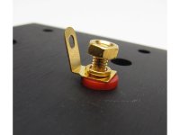
Perhaps your RCA input is grounding to the chassis instead of the GND 1. I think if you put the little washers on in the wrong order it can cuase the rca tab to ground to the chassis. Just a guess.
Thanks for the idea. I opened it up and checked it. There is no short between the RCA grounds and the back plate. There is a short between the RCA grounds and the base plate, as there should be.
I made a mistake in my earlier note. I have XLR pin 1 connected to GND on the circuit board, not GND2. I have the speaker output ground connected to GND2.
Hi,
Can I ask a question about the "Aleph 3"? or, more fenerally on the XLR input availability and the input impedance.
I checked the "Aleph J", "Aleph 1.2", "Aleph 2", "Aleph 5", "Aleph 4" and "Aleph M" circuits and all give the possibility of having a balanced input.
Strangely enough the "Aleph 3" doesn't give natively this opportunity.
I could attach the negative wire of the XLR input to the conjunction of the C1 and R7
Unfortunately in the original schema C1 and R7 are exchanged so that the same happens in the PCB's I can find.
With an unbalanced input this makes no difference, but the same is not true with unbalanced inputs.
Furthermore: what could be the most appropriate value for the R7 value? I have put R7=22.1k for symmetry. Correct?
Thanks
Can I ask a question about the "Aleph 3"? or, more fenerally on the XLR input availability and the input impedance.
I checked the "Aleph J", "Aleph 1.2", "Aleph 2", "Aleph 5", "Aleph 4" and "Aleph M" circuits and all give the possibility of having a balanced input.
Strangely enough the "Aleph 3" doesn't give natively this opportunity.
I could attach the negative wire of the XLR input to the conjunction of the C1 and R7
An externally hosted image should be here but it was not working when we last tested it.
Unfortunately in the original schema C1 and R7 are exchanged so that the same happens in the PCB's I can find.
With an unbalanced input this makes no difference, but the same is not true with unbalanced inputs.
Furthermore: what could be the most appropriate value for the R7 value? I have put R7=22.1k for symmetry. Correct?
Thanks
How do you like the sound of the Aleph vs. M2 ? I’m fixing to build either one but can’t decide what direction to go.
I haven't built an M2 - yet - but I can comment - subjectively - on the Aleph. Last weekend I had one of my long-time tube audiophile friends over to listen to the Aleph. He said something to the effect of: most neutral solid-state he's ever heard; can unravel complex music with a lot of detail. But an amp that doesn't draw attention to itself but just does an extremely competent job. The Aleph, however, doesn't have the "bloom" (coloration?) / midrange breath of the best tube amps.
As I said - subjective - so take it with a grain of salt.
Russellc,
I see back on page 117 of this thread, you were looking to wire your Aleph J with both XLR and RCA without a switch. Grimberg replied with what looks to be the same wiring as I am using. Did you follow grimberg's wiring, and did you use shielded or unshielded input wires? Do you have any noise when using RCA?
Thanks,
Alan
I have not yet installed the XLR jacks. A small shorting U shaped wire will do it, but switch seemed handy.
Russellc
Hi,
Can I ask a question about the "Aleph 3"? or, more fenerally on the XLR input availability and the input impedance.
I checked the "Aleph J", "Aleph 1.2", "Aleph 2", "Aleph 5", "Aleph 4" and "Aleph M" circuits and all give the possibility of having a balanced input.
Strangely enough the "Aleph 3" doesn't give natively this opportunity.
I could attach the negative wire of the XLR input to the conjunction of the C1 and R7
An externally hosted image should be here but it was not working when we last tested it.
Unfortunately in the original schema C1 and R7 are exchanged so that the same happens in the PCB's I can find.
With an unbalanced input this makes no difference, but the same is not true with unbalanced inputs.
Furthermore: what could be the most appropriate value for the R7 value? I have put R7=22.1k for symmetry. Correct?
Thanks
that can't be a problem to exchange places of cap and resistor on pcb , if pcb is made with that mistake
regarding R7 value , can you post your reference schematic for Aleph 3
I can tell right now what's needed , but better to keep with your reference , to avoid lost in translation effect
OK ... I need some help from the gurus ...
The Aleph J was working perfect and biased at 400mV with no offset. Played great for years. Packed it up to go test some speakers and planned on using the phone for a source. Much to my surprise the phone started at full volume and we heard ringing for a while. 😛
Got home and hooked the J backed up and now when I turn it on and off the speaker cones move a significant distance like there is DC offset during start-up and shut-down that it did not do before.
Went back in to check bias and offset and offset is still zero but bias was WAY low ~250mV. I cranked it to 350mV and re-zeroed offset. Let it warm another 30 minutes and it was down to 300mV. I cranked it up to ~390mV before the pots bottomed out (BOTH left and right channels acting the same). I re-zeroed offset but the amp seems WAY warmer than before! I started hearing creaking and cracking so I turned it off. I have not had a chance to measure the sink temp with my IR but can if it is helpful.
Any ideas? Do I screw something up blasting it full bore? 😱
Not saying this is your case but I had something very similar happen with my Aleph J and it ended up being a DMM issue. Once I tried a different multimeter (it was brand new with a fresh battery) I was able to get stable bias/offset readings that didn't decline with time.
The extra hot case with the lower (false) bias reading was also a big indicator that the DMM measurements were off, not the actual value.
besides DVM issues ,can you confirm same Iq on each mosfet , measuring across each source resistor?
besides that , if using unbal input , take care of having grounded neg input
besides that , if using unbal input , take care of having grounded neg input
The original circuit can be found in the "Aleph 3 Service Manual" as quoted by PASS LABS CLONE - ALEPH 3 Amplifier KK-PCB.that can't be a problem to exchange places of cap and resistor on pcb , if pcb is made with that mistake
regarding R7 value , can you post your reference schematic for Aleph 3
I can tell right now what's needed , but better to keep with your reference , to avoid lost in translation effect
The schematics is
An externally hosted image should be here but it was not working when we last tested it.
.
So, what can be an appropriate value for the resistance so that the input impedance, as seen by the XLR, is the same for both (+) and (-)?
Thanks again
R101 10K
R103 100K
R102 10K
R104 100K , put 6p8 to 10p across R104
C101 22uF Elna Silmic , put 1uF solid cap as bypass
also put same bypass across C103
in schematic you show us in post #3212 , just ignore (leave unpopulated) R7 position , and suddenly you'll have proper arrangement
R103 100K
R102 10K
R104 100K , put 6p8 to 10p across R104
C101 22uF Elna Silmic , put 1uF solid cap as bypass
also put same bypass across C103
in schematic you show us in post #3212 , just ignore (leave unpopulated) R7 position , and suddenly you'll have proper arrangement
Last edited:
- Home
- Amplifiers
- Pass Labs
- Aleph J illustrated build guide