I had some things I need to double check so deleted last post. It may be as you say, just close lid and enjoy.
Ok, double checked and the AC current through upper and lower source resistors, they are a perfect match on one side 0.333vrms (across 0.33R) while on the other channel it is 0.333vrms (upper) and 0.284vrms (lower) - close enough?
Anyhow, I think I am good with it now.
Ok, double checked and the AC current through upper and lower source resistors, they are a perfect match on one side 0.333vrms (across 0.33R) while on the other channel it is 0.333vrms (upper) and 0.284vrms (lower) - close enough?
Anyhow, I think I am good with it now.
Last edited:
Ok, I reran test at 100Hz AC to make sure DVM was picking up the measurement correctly. The ratio is 55% on left channel and 45% on right channel. Both at 2.0A bias current. DC offset is about 1mV to 10mV depending on state of warmup.
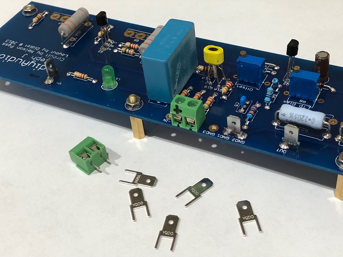
Looking at this photo, what values are you using in J1, J2, R6, ? They should be jumpers like you have in R30.
Last edited:
The 'official' schematic doesn't have the 562R on the emitter, but that schematic has been lost in the server update. (I need to re-build this guide, but I'll do it after board revisions)
The original doesn't have 220R in the Jfet gates either. R1 and R3 will do all the work of gatestoppers.
In your wiring, do you have -IN connected to GND? I can't tell from your photos.
The original doesn't have 220R in the Jfet gates either. R1 and R3 will do all the work of gatestoppers.
In your wiring, do you have -IN connected to GND? I can't tell from your photos.
Yes, -ve Input is tied GND with a wire jumper on bottom side of board. There would be no gain otherwise. I don’t think 220R is going to affect distortion when tacked onto 2k2. The 562ohms may change the bias set point but hard to see how it affects distortion.
-IN to GND --- good. 🙂
I'm not worried about the 220R either.
How much drop do you have over R8? Should be about 8v
I'm not worried about the 220R either.
How much drop do you have over R8? Should be about 8v
I’ve been meaning to check LTP current. Need to find some accessible pins or legs of resistors to check. 8v over 1k is 8mA. The R6 560ohms is actually very accessible, so about 4.48v?
There are pads on either side of the pot that will work perfectly, they are there to put a resistor in the place of the pot
You are right, about 4.5v over the 560 in the emitter.
The zener is the strongman in the CCS, everything is going to fall in line because of that, the pot is rather superfluous. It won't be on the next revision.
The zener is the strongman in the CCS, everything is going to fall in line because of that, the pot is rather superfluous. It won't be on the next revision.
-IN to GND --- good. 🙂
I'm not worried about the 220R either.
How much drop do you have over R8? Should be about 8v
I am measuring 5.54v across R8 on both channels. I guess this is a little on the low side and might cause higher distortion? I will adjust to get 8.0v.
Adjusting R8, the voltage across it maxes out 6.70v on one side and 6.80v on the other. Maybe that 560ohms needs to be replaced with a jumper?
Last edited:
I just remeasured the distortion with the higher LTP bias and it actually went up a bit. From 0.37% to 0.43%.
So I put it back to the older value for the LTP bias.
So I put it back to the older value for the LTP bias.
Last edited:
Does anyone have example of measurement spectrum from Aleph J? THD should be about 0.05% at 1w and 1kHz?
Does anyone have example of measurement spectrum from Aleph J? THD should be about 0.05% at 1w and 1kHz?
Are you using diyaudio store pcbs?
Yes, maybe it's all the spade connectors adding the distortion 🙂
- Home
- Amplifiers
- Pass Labs
- Aleph J illustrated build guide