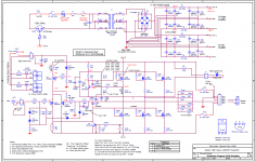
They are practically the same exceptI have stared at these two power supplies for a few minutes, could you point out the difference? I am not finding it! Old eyes...other than slight difference in the way "TH" drawn in schematic....and line cap.
Russellc
- The R1 version has a cap (should be a X2 safety cap) across the AC line. This cap helps eliminate the "spark" when the power switch is engaged.
- The R1 version also has a bleeder to drain the joules in the cap banks quickly after a power off.
I prefer the R1 version personally.
They are practically the same except
- The R1 version has a cap (should be a X2 safety cap) across the AC line. This cap helps eliminate the "spark" when the power switch is engaged.
- The R1 version also has a bleeder to drain the joules in the cap banks quickly after a power off.
I prefer the R1 version personally.
I think those are minor compared to the major changes to the output CRC topology:
There are independent outputs for Left and Right channels on the newer one. Meaning that they don’t share the exact same power rail which gives better stereo separation and imaging.
They are practically the same except
- The R1 version has a cap (should be a X2 safety cap) across the AC line. This cap helps eliminate the "spark" when the power switch is engaged.
- The R1 version also has a bleeder to drain the joules in the cap banks quickly after a power off.
I prefer the R1 version personally.
I do use a line cap and bleeder resistors. I used to forgo the bleeder resistors, as the amp drains it very quickly. I began using them again after testing a newly finished power supply, ( not hooked up to amp yet) and later touched the tip of a pair of mini excelite wire cutters, cutting the test wires HOURS later.....the resulting discharge blasted a small notch in the cutting edge....
Russellc
Last edited:
This is indeed a very common practice from the tube world to decouple 2 channels from one common power supply. It does provide some improvement over the other schematic with the same parts. However, both channels are still sharing the same power supply - the transformer, the bridge, and the first C. It isn't dual monos.
I will say, if you are doing point-2-point, go for it as there is no additional cost with some benefit. If you are using the power supply boards such as the one from diystore, don't loose sleep.
I will say, if you are doing point-2-point, go for it as there is no additional cost with some benefit. If you are using the power supply boards such as the one from diystore, don't loose sleep.
Yeah, you remind me that I had a "small" 35V 4700uF cap in my phono pre and had no bleeder. The unit had separate chassis for the preamp and the power supply. I forgot the 2 chassis were still connected when I was poking around in the preamp and managed to short the 2 pins in the XLR connector with my screw driver and made a notch to the edge. I was surprised how much energy such "small" cap still held after an hour. Suffice to say, lesson learned.I do use a line cap and bleeder resistors. I used to forgo the bleeder resistors, as the amp drains it very quickly. I began using them again after testing a newly finished power supply, ( not hooked up to amp yet) and later touched the tip of a pair of mini excelite wire cutters, cutting the test wires HOURS later.....the resulting discharge blasted a small notch in the cutting edge....
Russellc
1.7amps is 48C. I’m surprised that this 4U case is able to take this much heat. Maybe increase to 1.9amps? I’m willing to go to the 55C limit.
This is indeed a very common practice from the tube world to decouple 2 channels from one common power supply. It does provide some improvement over the other schematic with the same parts. However, both channels are still sharing the same power supply - the transformer, the bridge, and the first C. It isn't dual monos.
I was going to say pretty much what you said. Common in the tube world to split the PS section with an addition of a resistor and cap on the last section. Supposed gives better separation. I did this on my V-fet but added an extra 15K uf cap as well. Couldn't hurt, NP did it.
Ok, I took it to 2amps and it finally is at 54C at the hottest part and 51C elsewhere. I’ll leave it here. Also, driving it with the Aksa Lender Preamp. Wow! The dynamics and clarity are really superb. The preamp is very low distortion and able to drive any amp to clip yet stay clean.
Aleph J Measurements
Having let the amp burn in overnight at 2amp bias, I am pretty confident all the caps etc would have sufficient time to stabilize by now. I connected my usual 8ohm 25w load resistor (mounted to heatsink) and proceeded to connect my Focusrite 2i4 audio interface for the measurements. The moment I connect the load resistor voltage outputs to the ADC input, some sort of oscillation appears. This happens whether or not a SINE tone is playing. I took a second computer and had a separate Focusrite Solo produce the test tone and had the 2i4 read the signal then there was no oscillation. I have never observed this in any other amp I have tested. So I am wondering if maybe an input RFI filter network is needed. It is indeed absent on this amp.
Anyhow, I did not like the idea of using two Focusrites just to make a measurement. I created a high resolution, low distortion 1kHz test tone using Audacity. Put that FLAC file on my Cayin N3 DAP which has an AK4490 DAC reportedly, a very nice one. Thus, I will use the N3 as the tone generator DAC and the Focusrite 2i4 as the measurement ADC. And being separate devices, I do not have that strange feedback oscillation.
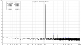
Here is the FFT of the N3 put directly into 2i4, you can see the distortion is very low (0.0009% THD) and all 2nd and 3rd harmonic:

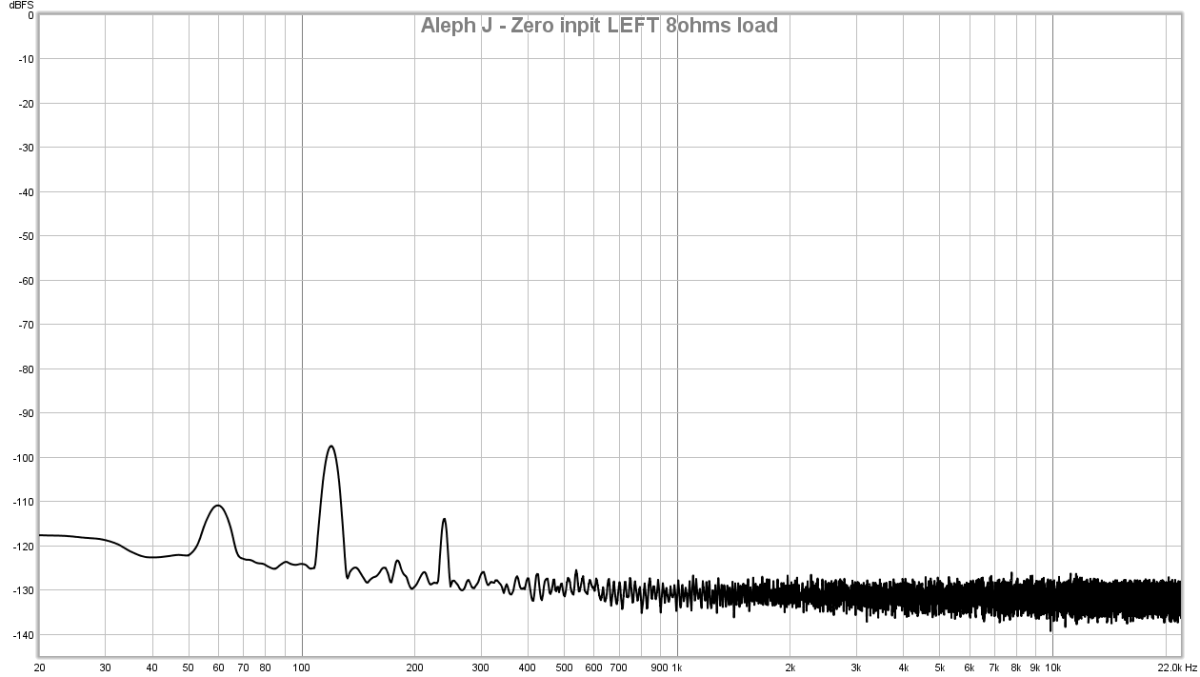
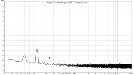
Here is the FFT of the Aleph J LEFT measured at the 8ohm load with zero input, the noise floor is nice and quiet except for the 120Hz and 180Hz bumps from the linear trafo F6 PSU:
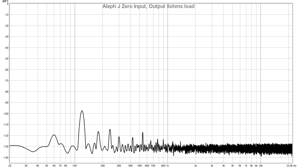
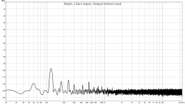
Here is the FFT of the Aleph J RIGHT with zero input:
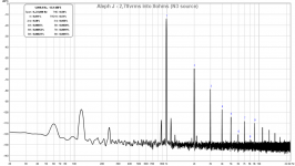
Here is the LEFT Channel FFT of the Aleph J with about 2.7vrms into 8ohms (I could not get 2.83vrms exactly due to the discrete volume adjustment on the N3):

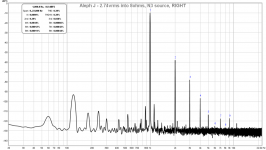
Here is the Right Channel FFT of the Aleph J with about 2.7vrms into 8ohms:
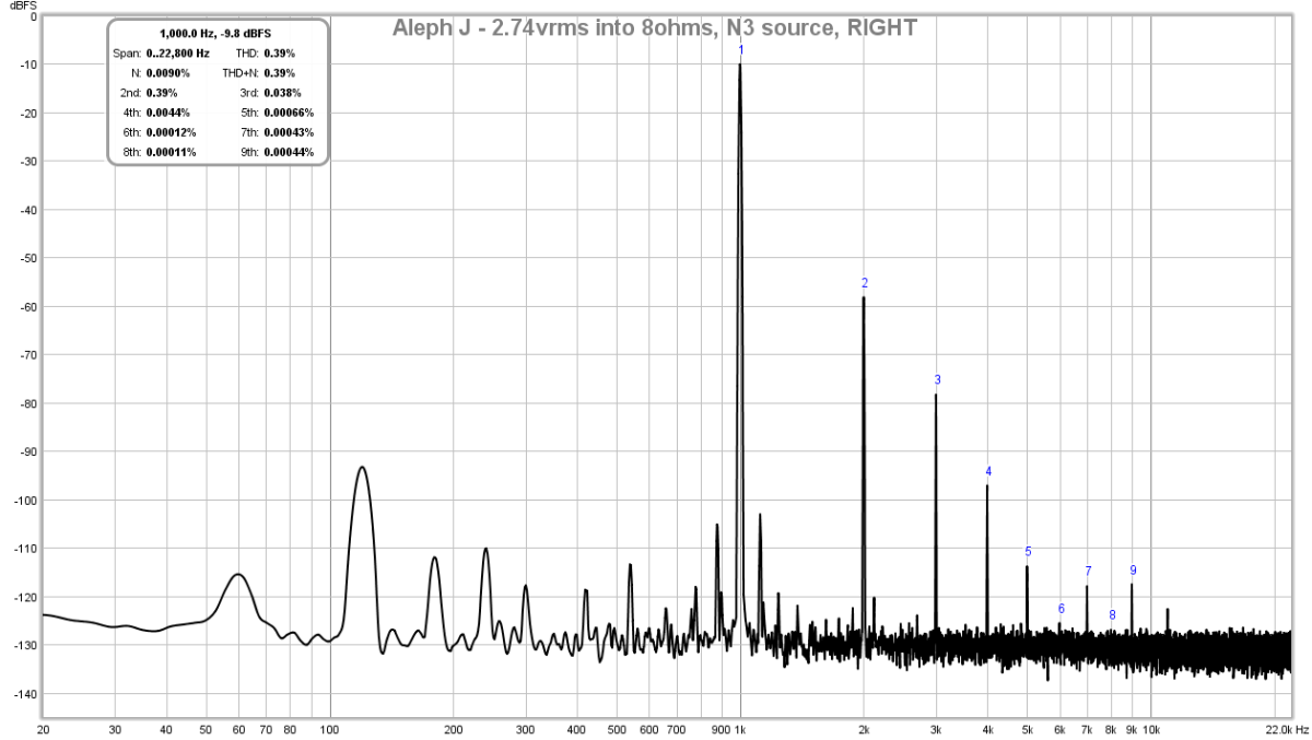
The THD is quite high for 1 Watt into 8ohms. The profile is nice with descending higher orders and 3rd is -20dB down from 2nd and so forth. And all this sounds very sweet to the ears, and probably very close to a SET tube amp, but maybe 10x less THD as those are in the 2% range. However, this is quite a bit more than what I was expecting, about 0.05% or thereabouts. So, I am wondering, is this normal? Has anyone else measured the FFT at 1W into 8ohms? As I recall, the Babelfish J was about in the same territory for THD so maybe this is really just a fact of the topology?
Don't get me wrong, I am not complaining, it sounds great and the noise is very low as you can see. Just wondering if I am missing something here.
Having let the amp burn in overnight at 2amp bias, I am pretty confident all the caps etc would have sufficient time to stabilize by now. I connected my usual 8ohm 25w load resistor (mounted to heatsink) and proceeded to connect my Focusrite 2i4 audio interface for the measurements. The moment I connect the load resistor voltage outputs to the ADC input, some sort of oscillation appears. This happens whether or not a SINE tone is playing. I took a second computer and had a separate Focusrite Solo produce the test tone and had the 2i4 read the signal then there was no oscillation. I have never observed this in any other amp I have tested. So I am wondering if maybe an input RFI filter network is needed. It is indeed absent on this amp.
Anyhow, I did not like the idea of using two Focusrites just to make a measurement. I created a high resolution, low distortion 1kHz test tone using Audacity. Put that FLAC file on my Cayin N3 DAP which has an AK4490 DAC reportedly, a very nice one. Thus, I will use the N3 as the tone generator DAC and the Focusrite 2i4 as the measurement ADC. And being separate devices, I do not have that strange feedback oscillation.
Here is the FFT of the N3 put directly into 2i4, you can see the distortion is very low (0.0009% THD) and all 2nd and 3rd harmonic:
Here is the FFT of the Aleph J LEFT measured at the 8ohm load with zero input, the noise floor is nice and quiet except for the 120Hz and 180Hz bumps from the linear trafo F6 PSU:
Here is the FFT of the Aleph J RIGHT with zero input:
Here is the LEFT Channel FFT of the Aleph J with about 2.7vrms into 8ohms (I could not get 2.83vrms exactly due to the discrete volume adjustment on the N3):
Here is the Right Channel FFT of the Aleph J with about 2.7vrms into 8ohms:
The THD is quite high for 1 Watt into 8ohms. The profile is nice with descending higher orders and 3rd is -20dB down from 2nd and so forth. And all this sounds very sweet to the ears, and probably very close to a SET tube amp, but maybe 10x less THD as those are in the 2% range. However, this is quite a bit more than what I was expecting, about 0.05% or thereabouts. So, I am wondering, is this normal? Has anyone else measured the FFT at 1W into 8ohms? As I recall, the Babelfish J was about in the same territory for THD so maybe this is really just a fact of the topology?
Don't get me wrong, I am not complaining, it sounds great and the noise is very low as you can see. Just wondering if I am missing something here.
Attachments
Last edited:

For comparison, here is what I managed to get with a MoFo at 2.83vrms, 0.14%THD and very clean only H2 and H3.
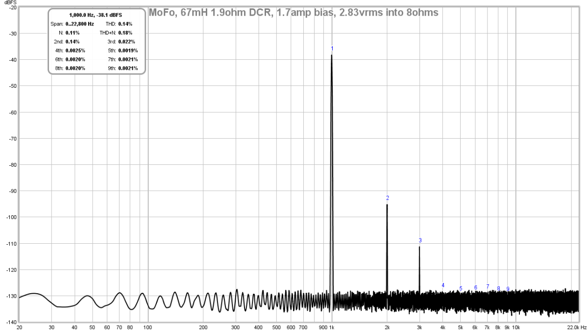
This has me scratching my head now a 1 transistor amp can do better than a more complex design with CCS.
This has me scratching my head now a 1 transistor amp can do better than a more complex design with CCS.
Last edited:
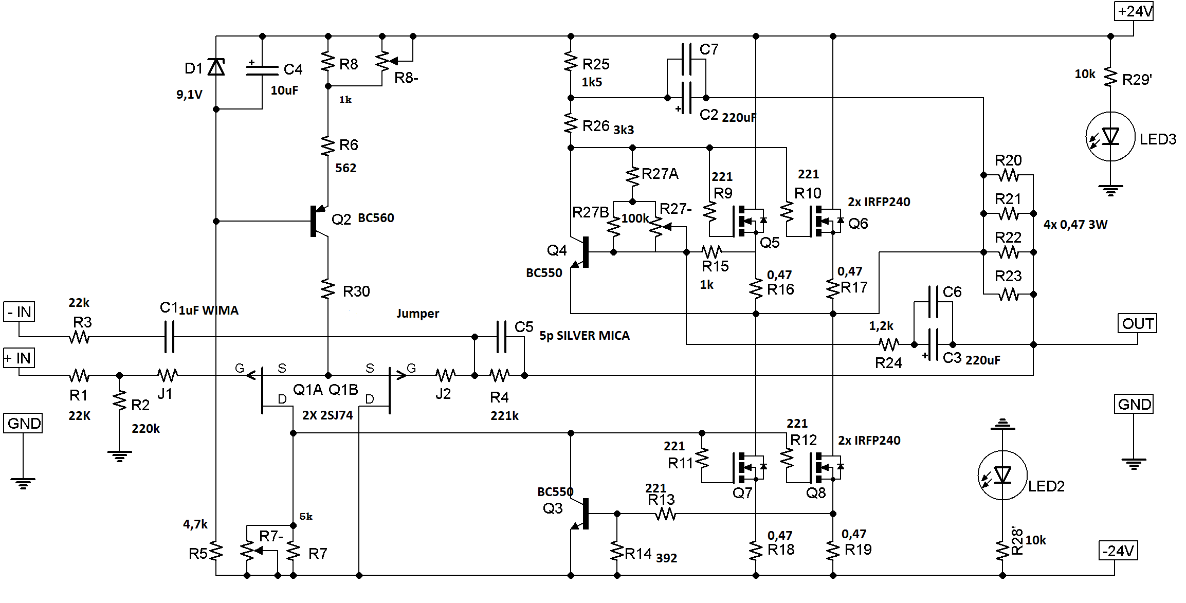
Which resistors will tell this? I followed the schematic values. The main FB gain is 20dB.
For R20 to R23 I am only using two Panasonic metal film 3W at 0.22R vs qnty 4 at 0.47R.
For R20 to R23 I am only using two Panasonic metal film 3W at 0.22R vs qnty 4 at 0.47R.
Last edited:
Ok, two things;
First, please set the 'bias' to 0.4v across the output device source resistor. (Either R18 or R19), reset offset, and re-measure your amp, and please post results here.
Once you've done that, then;
Read Zen 2, specifically the bit about the Aleph current source on page 3
http://www.firstwatt.com/pdf/art_zv2.pdf
Set R27 pot to get the 50% figure between the Mosfet source resistors (R16,17) and the sense resistors (R20-23)
Yes, this will adjust the bias. The pot marked 'bias' really isn't, although it does have that overall effect. That pot sets the AC current gain of the CCS.
I ran out of 0.47R resistors (actually misplaced whole bag of nice Panasonics). So I am using 0.33R resistors on R18 and R19. I currently have voltage across them set at 0.33V so 1amp through each. So I think the bias current is high enough.
I will read the section you indicate to understand what you mean by 50% figure.
Thanks,
X
Edit: ok, I read it and am not sure what is meant by the 50% figure. As the feedback at the sense resistor is for AC, what I am I looking for when adjusting R27? Do I need to feed it an excitation signal and then adjust R27 so that AC current in sense resistor is 50% of bias current through main source resistors ?
Last edited:
Ok, with 0.33 ohm resistors a similar bias value to suggested is 0.28v. (850mA) Set that to begin with a re-measure your distortion plot.
In the Zen 2 article read the paragraph that starts with "In any case, to achieve this 50%..."
In the Zen 2 article read the paragraph that starts with "In any case, to achieve this 50%..."
I did set the AC gain of the Aleph current source in my amp by using the following method:
Measure the AC voltage across R16 and R18.
50% is achieved when the two voltages are equal. (This assumes that the values of R16/R17 and R18/R19 are equal).
I also tried other gain settings for the Aleph current sources, for example 33% / 67% (voltage across R18 is double the voltage R16).
When I tried this, I always came back to 50%, which in my system sounded best ...
Best regards,
Claas
Thanks 6L6 and chede.
In the article, Mr Pass refers to adjusting R15 in the article Fig 6, which is R24 in the above schematic. That’s fixed at 1k2, should we make that a pot and adjust? Trying to see if overall bias current and AC CCS feedback can be decoupled?
In the article, Mr Pass refers to adjusting R15 in the article Fig 6, which is R24 in the above schematic. That’s fixed at 1k2, should we make that a pot and adjust? Trying to see if overall bias current and AC CCS feedback can be decoupled?
... <AC current gain> adjusting ... R24 in the above schematic. That’s fixed at 1k2, should we make that a pot and adjust?
That's what I did in my Aleph. I actually did not build it as an Aleph J originally, but as an Aleph Mini, which I later converted to "J".
So, change R24 to a pot to adjust Aleph Current Source gain.
Also, in my Aleph the upper connection of R27 pot actually goes to the connection between R25 and R26, not below R26.
In my amp, the setting of bias via R27 and AC Gain via R24 is independent of each other - no influence on the other when setting one of them.
For understanding the Aleph 3 / 30 / Mini / J, I think the great schematic of Algar_emi is still very helpful. (see attached).
All the best,
Claas
Attachments
irst, please set the 'bias' to 0.4v across the output device source resistor. (Either R18 or R19), reset offset, and re-measure your amp, and please post results here.
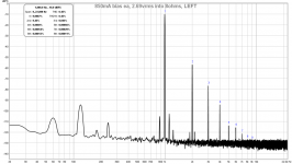
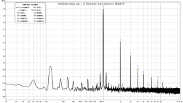
Here are the FFT's for the above case of 850mA bias current on each MOSFET or 1.7amps total bias.
LEFT:
RIGHT:
As you can see, the THD and profile looks about the same as before.
@Claas,
Thanks for the schematic by Algar_Emi. It loks substantially different with IRFP9610 as input stage and uses a lot of caps here and there to stop oscillation. Gives me ideas to try because I think my amp is prone to oscillation when I connect the output load to the input of my Focusrite. First thing to add is RFI filter on inputs. With a 22k input resistor, a 22pF cap to GND should work. Perhaps even a 33pF silver mica might do the trick, I have lots of those.
I will have to think about if it is worth removing everything to install the pot for AC gain setting.
Here is schematic extracted from above pdf for easy viewing directly:
Attachments
Last edited:
now , when you set both Iq and Aleph AC gain (no other explanation or condition than equal current swings through source resistors (lower comparing to upper) is needed) ..... close the lid and enjoy
be sure that Iq is set in temp equilibrium , ie. when lid is closed
one can fiddle more with current through LTP to decrease overall THD , but that demands readjusting everything
edit: or you can try to flip JFets (so drains in Tail ) , just to test useful conventions
be sure that Iq is set in temp equilibrium , ie. when lid is closed
one can fiddle more with current through LTP to decrease overall THD , but that demands readjusting everything
edit: or you can try to flip JFets (so drains in Tail ) , just to test useful conventions
- Home
- Amplifiers
- Pass Labs
- Aleph J illustrated build guide