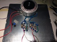
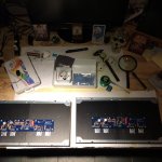
Here are some pictures of my completed Aleph J. I'm missing one of it with top and bottom and up and running. maybe I'll post them later.
For now, I just want to pay my respects to Mr. Pass, 6L6 and all those who contributed to this thread. Reading it was very useful, entertaining and educational.
The amp is powerful and the sound very clear.
Thank you all.
P.
For now, I just want to pay my respects to Mr. Pass, 6L6 and all those who contributed to this thread. Reading it was very useful, entertaining and educational.
The amp is powerful and the sound very clear.
Thank you all.
P.
Attachments
The amp is powerful and the sound very clear.
@ Patkhan
Superb DiY amplifier work

My Aleph J have similar sound clarity and transparency.
Now i think about installation of input XLR connectors because he ready accept both with RCA.
Balanced source audio card or server with preamp can be interesting to play together with Aleph J
Balanced and Unbalanced Connections | PreSonus
Kindest regards
Originally Posted by patkhan1  The amp is powerful and the sound very clear.
Now I have it paired to a Transcendent Sound Grounded Grid Pre modified for high gain (30 dB) for my F4. The combo were outputting about 97dB with the pre at less than 25% volume. And I hadn't even noticed that it was so loud before meassuring. Just clear highs and gut felt bass.
Amazing.
The amp is powerful and the sound very clear. Now I have it paired to a Transcendent Sound Grounded Grid Pre modified for high gain (30 dB) for my F4. The combo were outputting about 97dB with the pre at less than 25% volume. And I hadn't even noticed that it was so loud before meassuring. Just clear highs and gut felt bass.
Amazing.
Hello
I build the Aleph j pcb , and i have same Problem like other , after some evenings searching the mistake , i find out that ztx 450 and ztx 560 has not the right Direktion ,so I search for some photos ,but i cant find a 100 prozent good phote to be shure ,and see the right position , because the corner of the ztx are so small ,
.
I have at the loudspeaker output 27 V dc ,very wrong.
some parts get hot , irf`s stay cold , and I turn of the power,
so i test the ztx 560 and turn it, hold it with my fingers ,and put it to the solder points on the pcb .
And a wunder 27 DC dissepeard and the irf`s get hot on the heatsink.
So the problem hasn`t endet. After soldering and turning the ztx I have the same problem 27 Volt dc . I also turn the ztx 450 ,but my be it is wrong . my by th ztx broken, because to hot soldering.
I order some ztx also bc 550 and 560 and 9.1 diode , around this parts i hope is the solution.
so befor I solder the new parts i need 99 prozent good photo ore something else of the 3 ztx
my be sombody here of the aleph-genius can help me .
best regards Andreas
Andreas,
The PCB has markings for each of the pins: (E)mitter, (B)ase, (C)ollector. Look at the datasheets linked below to identify the pins on each device and correctly place them on the board.
https://www.diodes.com/assets/Datasheets/ZTX450.pdf
https://www.diodes.com/assets/Datasheets/ZTX550.pdf
The PCB has markings for each of the pins: (E)mitter, (B)ase, (C)ollector. Look at the datasheets linked below to identify the pins on each device and correctly place them on the board.
https://www.diodes.com/assets/Datasheets/ZTX450.pdf
https://www.diodes.com/assets/Datasheets/ZTX550.pdf
Hello Grimberg and other Folk`s
The First pcb is running .
I take care to solder the ztx in the right position , check all resistor`s.
I have DC Offset around 0,0 but its not all finish , I worm up only a little moment 5 minutes ore so , and i am waiting of a 100 k poti ,they send 1 k , bad .
I will tell you when the the music is playing.
Thank you
Aleph J heatsink temperatures
Hello All,
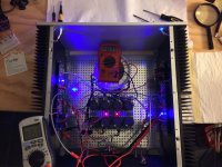
I’ve had my Aleph built for a while and decided to check my bias and offsets to see if anything had drifted, all was on spec of 400 mv bias and 0-.4 mv offset, its in a 4U chassis. I also bought an infrared heat gun to check the heat sink temperatures. My ambient room temperature is around 22 degrees Celsius, and from a distance of 12” & 24” the heat sink temp was 48.9 degrees Celsius from mid way up the heat sink all the way to the top. I thought that this was a little low based on the build guide that said it could be as high as 55 degrees. I also checked the temperature on all of the output transistors pins and they also read less than 50 degrees, the build guide suggests that the middle pin should be no more than 65 degrees but it’s the same temperature as pins 1 & 3. I’m not sure if this all jives. I’ve measured other things with the gun and it seems to be reading temperature correctly.
I’ve now raised the bias to 440 mv and the temperatures have increased by about 2 degrees. At this point I can’t leave my hands on the heat sinks for more than 5-6 seconds before it becomes uncomfortable. Can I leave it like this or should I turn the bias back down to 400mv?
Any advice or insite on the temp readings I’m getting would be greatly appreciated.
Hello All,
I’ve had my Aleph built for a while and decided to check my bias and offsets to see if anything had drifted, all was on spec of 400 mv bias and 0-.4 mv offset, its in a 4U chassis. I also bought an infrared heat gun to check the heat sink temperatures. My ambient room temperature is around 22 degrees Celsius, and from a distance of 12” & 24” the heat sink temp was 48.9 degrees Celsius from mid way up the heat sink all the way to the top. I thought that this was a little low based on the build guide that said it could be as high as 55 degrees. I also checked the temperature on all of the output transistors pins and they also read less than 50 degrees, the build guide suggests that the middle pin should be no more than 65 degrees but it’s the same temperature as pins 1 & 3. I’m not sure if this all jives. I’ve measured other things with the gun and it seems to be reading temperature correctly.
I’ve now raised the bias to 440 mv and the temperatures have increased by about 2 degrees. At this point I can’t leave my hands on the heat sinks for more than 5-6 seconds before it becomes uncomfortable. Can I leave it like this or should I turn the bias back down to 400mv?
Any advice or insite on the temp readings I’m getting would be greatly appreciated.
heatsink up to 55 somewhere on mid top
thermal interface between mosfet and heatsink is OK if mosfet case/pins/etc aren't at more than 10C comparing to heatsink in mosfet's vicinity
thermal interface between mosfet and heatsink is OK if mosfet case/pins/etc aren't at more than 10C comparing to heatsink in mosfet's vicinity
Hi Zen Mod, thanks for your reply. I’ve just rechecked the heatsink temps and they are 51 - 51.5 degrees and the highest temp on any place around the Mosfets including the pcb is no more than 60 degrees. So that would indicate that’s all is ok, correct?
I have assembled the ACA Kit and really liked it. Now I want to try the Aleph J. Just a few questions. Is there a difference between the original Aleph J circuit and the DIY circuit? Is there a difference in sound quality between the two, provided you use all the recommended parts from the BOM pdf?
Last question. Why is the Toshiba 2S174-BL the preferred JFET? How much better is it compared to a substitute? Thanks.
Last question. Why is the Toshiba 2S174-BL the preferred JFET? How much better is it compared to a substitute? Thanks.
Last edited:
DIY Aleph J is close to original Aleph J , regarding sound quality
instead of Toshibas , you can use ( as exact equivalent in this circuit) LSJ74B from store
another solution is J271 (no prefix!) , matched pair , of course
or you can look for Babelfish J , as solution for least complicated build
(that was blatant commercial plug )
)
or - read newest Babelfish J thread for plenty of practical info , then make your own , with parts scavenged wherever you can find them
instead of Toshibas , you can use ( as exact equivalent in this circuit) LSJ74B from store
another solution is J271 (no prefix!) , matched pair , of course
or you can look for Babelfish J , as solution for least complicated build
(that was blatant commercial plug
)or - read newest Babelfish J thread for plenty of practical info , then make your own , with parts scavenged wherever you can find them
aleph J and babelfish J
Hi Try this,
Aleph J Versus Babelfish J V2
NS
where can I get more information on Babelfish J? Is that comparable to the Aleph J? Class A?
Hi Try this,
Aleph J Versus Babelfish J V2
NS
referring to https://linearaudio.net/sites/linearaudio.net/files/LSJ74_09_OCT_2009_PRELIMINARY.pdf
LS established same ranging as Toshiba , just calling them differently
so A is same as GR (green) , 2.6 to 6mA
B is same as BL (blue) , 6 to 12mA
C is same as V (violet) , 12 to 20mA
so , if you have A/GR ones , you can use them in Aleph J circuit (there (CCS) biased to approx. 5mA) , if they're in top of range , with Idss (gate at source potential) of 5 to 6mA
if they're wimpier , just parallel two in each position
what few clever and cunning members researched - they even doesn't need to be matched , all that matters is that sum of Idss is same for left and right side of LTP
- Home
- Amplifiers
- Pass Labs
- Aleph J illustrated build guide