Thanks I used your advice while building BA3 pre....had messed up my matched pair while building F5...2 parallel 74’s grade A saved the day...did not match them...just their total Idss value was same as grade B...BTW, the ones I have are in range of ~5mA
AlephJ seems to be the least explained articles from FW site...it is an enhancement of few type of Amps..-apart from Zen variations 2 article, can anyone suggest more info around the making of the circuits...not sure if it could be as detailed as F5....
Also, looks like IRFP240’s are going out of production...any true replacements...9240’s somehow are still available though they are complementary
Also, looks like IRFP240’s are going out of production...any true replacements...
Are you including IRFP240PBF in that statement? The lead-free part seems to still be readily available.
I have bought the 5. generation part, used in ACA and Aleph J, and i like this one.Also, looks like IRFP240’s are going out of production...
IRFP250MPBF Infineon Technologies | Mouser Deutschland
So alternatively could use the more modern, stronger one
Long-tailed pair and IDss
Let's assume that the Aleph J is designed for 8mA IDss LTP JFETs. We want to run the JFETs in the flat part of their curve, so the current needs to be somewhere between, say 4mA and 8mA.
Now let's assume that 14mA IDss parts are used instead. We need to run those a bit hotter, say 8mA to 14mA, to stay in the flat part of the curve. I assume we want the output stage to see the same voltage swing, and that this would be done by decreasing the value of R7? And at that point everything would be the same bar a slightly higher dissapation for the amp?
Thanks,
Jeff.
value of R7 is directly setting Iq of outputs
yes , need to be decreased if you increase Iq of LTP
however , if you set outputs to same Iq as in original , I can't see where increased dissipation comes from , except if you count increased dissipation of input JFets ..... which is important as fly's fart
yes , need to be decreased if you increase Iq of LTP
however , if you set outputs to same Iq as in original , I can't see where increased dissipation comes from , except if you count increased dissipation of input JFets ..... which is important as fly's fart
You da man, ZM.
(And yes, it was the fly fart I had in mind. Just wanting to make sure I understood what I was talking about. 😀)
(And yes, it was the fly fart I had in mind. Just wanting to make sure I understood what I was talking about. 😀)
Hi,
I'd like to build an Aleph J with CLC filter using Hammond chokes.
There are three chokes that seems to be suitable:
159ZJ 10mH 5A RDC=0.16R
159ZG 15mH 4A RDC=0.25R
159ZE 28mH 3A RDC=0.43R
The question is what is the max current draw per positive and negative rail in no-monoblock mode?
Best regards,
Maciek
I'm using Hammond 159ZL (2.5 mH / 10 A / Rdc=0.044R).
But then, I'm running my Aleph J at 2 A bias per channel. So each choke carries 4 A at idle 🙂
Very good results, amp is absolutely silent into 100 dB / W speakers.
Best regards,
Claas
But then, I'm running my Aleph J at 2 A bias per channel. So each choke carries 4 A at idle 🙂
Very good results, amp is absolutely silent into 100 dB / W speakers.
Best regards,
Claas
As a matter of fact it is to be an CRCLC circuit like this:
47000uF + 1R +100000uF +10mH + 100000uF
According to PSUD the DC voltage pulsing (is it a good word?) is about 18uV, which seems to be an overkill. But... as they say... bigger (lower) is better 😉
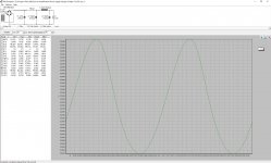
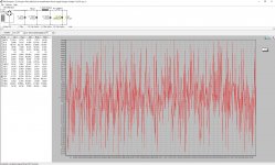
I tried to simulate bypass capacitor in PSUD but the effect is a little bit strange. Pictures in attachment.
Can someone tell me if it's caused by limitations of PSUD software, as I can't put less than 1mR resistance for by-pass capacitor? Or the bypass cap adds some distortion?
Andrea Ciuffoli in one of his projects wrote that amplifier with bypass caps in PSU sounded worse than without them.
Best regards.
Maciek
47000uF + 1R +100000uF +10mH + 100000uF
According to PSUD the DC voltage pulsing (is it a good word?) is about 18uV, which seems to be an overkill. But... as they say... bigger (lower) is better 😉
I tried to simulate bypass capacitor in PSUD but the effect is a little bit strange. Pictures in attachment.
Can someone tell me if it's caused by limitations of PSUD software, as I can't put less than 1mR resistance for by-pass capacitor? Or the bypass cap adds some distortion?
Andrea Ciuffoli in one of his projects wrote that amplifier with bypass caps in PSU sounded worse than without them.
Best regards.
Maciek
Attachments
Hi Maciek,
I've had PSUD2 freak out on me at times too; I always assumed it was just limitations in the software algorithms.
That being said, that's a LOT of capacitance you're planning. It's going to put a lot of stress on your transformer and rectifiers. I generally target < 100uV of ripple, and I'd be willing to bet even that is overkill.
I don't think bypass capacitors at the PSU do much. You're going to have a couple of mR of resistance in the wires between them and your transistors. A bypass on the actual amplifier channel boards will do much more good.
Cheers,
Jeff. (A relative noob, so take my advice with a grain of salt....)
Hi Maciek,
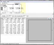
here is the PSUD simulation of the PSU that I currently use in my Aleph J (with just one upper and one lower IRFP140, and at 2 A per side):

As I said, silent into 100 dB/W speakers. Not the slightest trace of hum, and only the faintest bit of hiss with my ear "in the speaker driver". The hiss doesn't come from the PSU.
The 66,000 µF as the first cap is paralleled 33,000 µF caps. This I had done mainly to help the first cap deal with the ripple current, which can get quite high - look at the RMS value of I(C1) in the simulation.
I have actually a 2.2 µF WIMA MKP cap as a bypass cap for C2, but haven't tried to simulate it. As I haven't tried the PSU without it, I can't speak to it's effect on sonics 😛.
Best regards, Claas
here is the PSUD simulation of the PSU that I currently use in my Aleph J (with just one upper and one lower IRFP140, and at 2 A per side):
As I said, silent into 100 dB/W speakers. Not the slightest trace of hum, and only the faintest bit of hiss with my ear "in the speaker driver". The hiss doesn't come from the PSU.
The 66,000 µF as the first cap is paralleled 33,000 µF caps. This I had done mainly to help the first cap deal with the ripple current, which can get quite high - look at the RMS value of I(C1) in the simulation.
I have actually a 2.2 µF WIMA MKP cap as a bypass cap for C2, but haven't tried to simulate it. As I haven't tried the PSU without it, I can't speak to it's effect on sonics 😛.
Best regards, Claas
Attachments
Mhgawel
Check out how much current each cap is sinking.
You might find the first cap is sinking more current than it is rated for.
If that is the case double the first cap so it looks like CCRCLC
Check out how much current each cap is sinking.
You might find the first cap is sinking more current than it is rated for.
If that is the case double the first cap so it looks like CCRCLC
Last edited:
My first cap in PSU is rated for 16.2A and PSUD simulation shows about 14.2A so it's too close.
I think that I'll put 100mF 63V as a first cap. It's rated for 31.5A.
So it will be: 100mF + 1R + 100mF + 10mH + 47mF
The question is what is the proper value for I1 (constant current sink) when I simulate AJ biased to 400mV = 0.85A with PSU common for both channels?
Best regards, Maciek
I think that I'll put 100mF 63V as a first cap. It's rated for 31.5A.
So it will be: 100mF + 1R + 100mF + 10mH + 47mF
The question is what is the proper value for I1 (constant current sink) when I simulate AJ biased to 400mV = 0.85A with PSU common for both channels?
Best regards, Maciek
- Home
- Amplifiers
- Pass Labs
- Aleph J illustrated build guide