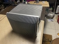
I think your heatsink is too "shiny" for infrared thermometer.The temperature of the hottest part of the heat sink after an hour.
Real temperature could be higher.

Yup, the shiny washers will not give an accurate reading. Apply a piece of kapton tape to the heatsink and aim at that 😉
I don’t have any kapton tape at hand. Can I use a permanent marker to darken a patch to take a reading instead? Also, the washers are obviously cooler to the touch than the heat sinks, which I was not expecting. Is this normal?
Just read it. I’ll stick to 400mV. As it is, when I measure all the output devices across their associated resistors, I get from 400-406 mV. Is this considered normal?Tizman looking good, "Does this mean that I can bias hotter? " you could but why ? reread post #8,678
It seems strange but it is normal. The heat conductivity between MOSFET plastic case and the washer is negligible, compared to the MOSFET metal part of the case and the heatsink. I actually just tried this with my Aleph J - I turned it ON from cold.... and yes... the heatsink around the MOSFETs gets hotter, compared to the washer.I don’t have any kapton tape at hand. Can I use a permanent marker to darken a patch to take a reading instead? Also, the washers are obviously cooler to the touch than the heat sinks, which I was not expecting. Is this normal?
This means that all the MOSFETs are conducting the same amount of bias current - hence just keep monitoring these voltage drops across the resistors for a while, re-tighten the screws in a few days... confirm the bias is still around 400mV.... (6mV tolerance is nothing - that's actually pretty good) and stop using the thermometer.Just read it. I’ll stick to 400mV. As it is, when I measure all the output devices across their associated resistors, I get from 400-406 mV. Is this considered normal?
Sorry, I used the thermometer one last time. I left the amp on for 1.5 hours, and the hottest spot I could find was 43 degrees Celsius. This was on the inside of the heat sinks in between the pairs of output mosfets. I made a dark spot with magic marker and measured there.It seems strange but it is normal. The heat conductivity between MOSFET plastic case and the washer is negligible, compared to the MOSFET metal part of the case and the heatsink. I actually just tried this with my Aleph J - I turned it ON from cold.... and yes... the heatsink around the MOSFETs gets hotter, compared to the washer.
This means that all the MOSFETs are conducting the same amount of bias current - hence just keep monitoring these voltage drops across the resistors for a while, re-tighten the screws in a few days... confirm the bias is still around 400mV.... (6mV tolerance is nothing - that's actually pretty good) and stop using the thermometer.
I plugged the amp into an ancient pair of high sensitivity alnico speakers I have to test.. With nothing plugged into the RCA inputs, there is no noise in one channel, and a slight hum in the other. When I shut off the amp, there is a loud motorboat noise for a half second or so. I put the amp on a pair of Klipschorns, and there is a definite audible hum in one channel. I wouldn’t want to shut the amp off with the Khorns connected so I unplugged the speaker cables before turning the amp off.
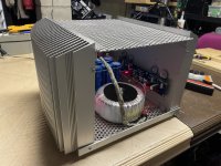
Here is a photo without a faceplate...View attachment 1097662View attachment 1097663View attachment 1097664View attachment 1097664
Attachments
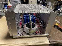
Here is a photo without a faceplate...View attachment 1097662View attachment 1097663View attachment 1097664View attachment 1097664
It is not impossible that your fairly low temp readings are correct with those cool large heatsinks. 🙂👍
But before you crank things up use a regular HQ food thermometer to double check the temps. And to paste black tape on any shiny surface if you want to measure with a contactless IR-meter.
Thanks! I am very pleased with how it turned out aesthetically. How would I go about chasing down the hum in one of the channels? My speakers are 104 DB/W/M. I’m guessing that it would be more difficult to hear the hum in a speaker with more normal sensitivity, but it is definitely audible at the listening position with nothing plugged into the inputs. The quiet channel is as, ot more quiet, than any other amp I own. Also of concern is the very loud sound at shut off. I am worried that I will damage my speakers.That looks wonderful!

The sinks are just warm to the touch, and not at all hot. I also have a pair of the older style ACA mono blocks, and they are obviously much hotter. I tried darkening the hottest part of the interior heatsink with black marker and measuring, and got 43 degrees Celsius.It is not impossible that your fairly low temp readings are correct with those cool large heatsinks. 🙂👍
But before you crank things up use a regular HQ food thermometer to double check the temps. And to paste black tape on any shiny surface if you want to measure with a contactless IR-meter.
With 104dB speakers every little detail may make a difference.
Here is some very useful information by diyAudio member Bonsai:
Ground Loops
More guidelines
Minimizing loop areas of wires that form a circuit by twisting them together is helpful for noise control.
To address cross channel ground loop in Aleph J, see diyAudio member Extreme Boky's post:
Aleph J mod
Is it audible with the inputs shorted or with a source connected?Thanks! I am very pleased with how it turned out aesthetically. How would I go about chasing down the hum in one of the channels? My speakers are 104 DB/W/M. I’m guessing that it would be more difficult to hear the hum in a speaker with more normal sensitivity, but it is definitely audible at the listening position with nothing plugged into the inputs. The quiet channel is as, ot more quiet, than any other amp I own. Also of concern is the very loud sound at shut off. I am worried that I will damage my speakers.
Yes, follow Ben’s advice. But if you want advice for possible easy fixes, we need to eyeball the PSU and specifically the grounding layout. Post a few well lit pics of the internals of your IMMACULATE build if you want 🙂
Sorry, I used the thermometer one last time. I left the amp on for 1.5 hours, and the hottest spot I could find was 43 degrees Celsius. This was on the inside of the heat sinks in between the pairs of output mosfets. I made a dark spot with magic marker and measured there.
I plugged the amp into an ancient pair of high sensitivity alnico speakers I have to test.. With nothing plugged into the RCA inputs, there is no noise in one channel, and a slight hum in the other. When I shut off the amp, there is a loud motorboat noise for a half second or so. I put the amp on a pair of Klipschorns, and there is a definite audible hum in one channel. I wouldn’t want to shut the amp off with the Khorns connected so I unplugged the speaker cables before turning the amp off.
Just to add to what's already provided in the above posts, there are 3 critical voltages on the schematics that will set the DC operating values of the whole amplifier. Make sure they are all good. Double-check the bias through the MOSFETs and confirm that R16 - R19 are all good (0.47ohms).
Aleph J may require a ground lift resistor when used with a single-ended RCA input, to team the slight hum/buzz. This hum/buzz will be audible on both channels - equally, and will not cause what you are experiencing - which is the loud motorboat noise when turning the amplifier OFF. The most likely root cause for this motorboat noise is the input differential pair... and possibly the active current source transistor Q4.
You could also use a good working side (PCB) as a reference point, i.e. compare the bad side with a good working side.
I'd do the ground lift mod first, replace the Q4 second, and then replace the JFETs last.... just make sure what I mentioned above is all good first. Or, do all 3 in one go... while the PCB is removed.
Post some close-up well-lit photos. Make sure the braided shield mains wire is not resting on top of those filter caps.
Good luck. The build looks great - such a shame you have that issue with one channel.
Thanks. I will read through, troubleshoot and report back.With 104dB speakers every little detail may make a difference.
Here is some very useful information by diyAudio member Bonsai:
Ground Loops
More guidelines
Minimizing loop areas of wires that form a circuit by twisting them together is helpful for noise control.
To address cross channel ground loop in Aleph J, see diyAudio member Extreme Boky's post:
Aleph J mod
Most kind. I would have actually preferred to put the power supply in a separate chassis and used an umbilical with an additional final capacitor in the signal chassis, but it has sat on the bench for so long that i just wanted to get it done as per the original plan. My primary concern is that the power transformer is too close to the boards. I'll work through the articles referred to by Ben Mah and see where that takes me. I will also get some photos at that point and post them.Is it audible with the inputs shorted or with a source connected?
Yes, follow Ben’s advice. But if you want advice for possible easy fixes, we need to eyeball the PSU and specifically the grounding layout. Post a few well lit pics of the internals of your IMMACULATE build if you want 🙂
Thanks for the annotated schematic. I'll check these voltages and report back.Just to add to what's already provided in the above posts, there are 3 critical voltages on the schematics that will set the DC operating values of the whole amplifier. Make sure they are all good. Double-check the bias through the MOSFETs and confirm that R16 - R19 are all good (0.47ohms).
Aleph J may require a ground lift resistor when used with a single-ended RCA input, to team the slight hum/buzz. This hum/buzz will be audible on both channels - equally, and will not cause what you are experiencing - which is the loud motorboat noise when turning the amplifier OFF. The most likely root cause for this motorboat noise is the input differential pair... and possibly the active current source transistor Q4.
You could also use a good working side (PCB) as a reference point, i.e. compare the bad side with a good working side.
I'd do the ground lift mod first, replace the Q4 second, and then replace the JFETs last.... just make sure what I mentioned above is all good first. Or, do all 3 in one go... while the PCB is removed.
Post some close-up well-lit photos. Make sure the braided shield mains wire is not resting on top of those filter caps.
Good luck. The build looks great - such a shame you have that issue with one channel.
View attachment 1097859
I went through the amp and shortened and rerouted all the wiring. With nothing plugged into the RCA inputs, the amp is absolutely dead quiet in one channel, and has a faint hum/buzz in the other channel. When shorting plugs or cables from the source are plugged in, there is a slight hum/buzz in the previously silent channel, and a louder hum buzz in the noisy channel. My guess is that there isn't a grounding issue, and that there is a bad component or soldering problem on the one noisy board. When I built the amp boards a long time ago, the BOM I used called for a 500 Ohm pot in the the LTP Bias space. This was apparently an error, as that is supposed to sit at 1K Ohm, so I replaced the pots with 1K resistors without removing the boards. I did this by rocking the pots back and forth slowly (they were not installed tightly to the board) until they snapped off, and then I put in a 1K Ohm resistor in their place. Unfortunately, on the board I'm having a problem with, I accidently removed the 2K Ohm pot at R7 instead of the LTP Bias pot. I replaced that pot with another pot, but did it without removing the board, and didn't do a good job. When I removed the R30 jumper and R7 to get to the pot, I tore out the trace on one side of the R30 jumper. All in all a mess that wouldn't have happened had I done the right thing and removed the board and done it properly. I am going to test voltages first as per your post, and then report back. Here are some closeups of the interior....Just to add to what's already provided in the above posts, there are 3 critical voltages on the schematics that will set the DC operating values of the whole amplifier. Make sure they are all good. Double-check the bias through the MOSFETs and confirm that R16 - R19 are all good (0.47ohms).
Aleph J may require a ground lift resistor when used with a single-ended RCA input, to team the slight hum/buzz. This hum/buzz will be audible on both channels - equally, and will not cause what you are experiencing - which is the loud motorboat noise when turning the amplifier OFF. The most likely root cause for this motorboat noise is the input differential pair... and possibly the active current source transistor Q4.
You could also use a good working side (PCB) as a reference point, i.e. compare the bad side with a good working side.
I'd do the ground lift mod first, replace the Q4 second, and then replace the JFETs last.... just make sure what I mentioned above is all good first. Or, do all 3 in one go... while the PCB is removed.
Post some close-up well-lit photos. Make sure the braided shield mains wire is not resting on top of those filter caps.
Good luck. The build looks great - such a shame you have that issue with one channel.
View attachment 1097859
This is where I messed up. You can see the thinner orange wire at R30.
- Home
- Amplifiers
- Pass Labs
- Aleph J illustrated build guide