
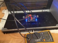

Having two MOSFETs so close can't be good for the heat transfer. Also, the heat dissipation per MOSFET of 40W (or more 😱) with that combination of having them tightly packed on a heatsink, is asking for trouble. The FW clones do not have any speaker protection; if one device fails, the speaker would burn in a fraction of a second.
Maybe with different Mosfets. Try the FQH44N10 and ceramic insulators. They like 26V rails and 1.8A bias. Not 55W per device, but great sound.Dare 55 watts?
I believe Baby Viking is using IRFP150, as prescribed
I know for several amps, mosfets cranked to 45 and even 50W, Keratherm and proper heatsinking -- working for years
though, 4U/400 (I believe that's on pic) is not covering 100W per side
80 is more realistic, and even then I like to use Babysitter during Summer, not because of mosfets but to keep caps chillier
That heatsink appears to be a 5U 400mm, so any worries about the output devices too close are not to worry about. 🙂
Maybe with different Mosfets. Try the FQH44N10 and ceramic insulators. They like 26V rails and 1.8A bias. Not 55W per device, but great sound.
Nice find/suggestion. I always go straight to capacitance vs DS voltage graphs in the case of FW amps.... where only one JFET provides voltage gain and all the drive capability. The FQH44N10 seems to be superior to IRFP150, albeit with lower dissipation. But, for those who live dangerously, it seems a clear winner.
Baby berserker McDaddypants is using 5U 400, Infineon IRFP150s (paired not matched per se), Keratherm @ 0.85N, and split washers. We have no summer, so 50 watts per device is goal. But since I am a bit of a fraidy cat, I might crank it down to 80-90 per sink during no-frost days of the year 
Last edited:
Hi all,
I had a mishapp when stuffing the boards. I changed places on one of the ztx450 transistors and the 550 transistor. Im now a bit concerned I might have over heated them when un- and re-souldering them to the boards. I havent powered up the boards yet but when I do, is there something I should look out for ( except the obvious flashes and smoke 😉) to tell if these devices have been damaged in any way? Or better yet, is there a way for me to determine this before putting power to the boards?
B.R Jakob
have universal tester, or Hfe function on DMM?
if no, test them with diode test
ggl will show how
if no, test them with diode test
ggl will show how
Yes, thanks for the tip. I used the dioder tester but since ( i suspect) the transistors are souldered in place i dont get the expected voltage drop. However both the npns measure the same and so do the pnps. I have spares but if avoidable id like to keep them as spares ��
Sounds good. Have variac? If so, good to use. If not, just switch on and quite wuickly off the first time, in case somethings off.
Monitoring source resistors is a good idea. Ensuring low or no IQ at first power on may be a good idea, at least on problem chan.
Monitoring source resistors is a good idea. Ensuring low or no IQ at first power on may be a good idea, at least on problem chan.
- Home
- Amplifiers
- Pass Labs
- Aleph J illustrated build guide