Thanks for your efforts to measure and post the results! I'm always a HUGE fan of actual data! That's quite a nice difference you have there! This is the equivalent of using larger (more expensive) sinks, or a better thermal interface...
As for bias, it will wander as long as temps vary. Let it run for 1+ hours before measuring/adjusting. Then, realize that it will change as soon as you remove the cover, or blow on them, or if the furnace/AC is running, if it is summer vs winter, or you have a ceiling fan running. Get it "close" and then forget about it. The same is true for offset.
It's faaaaar better to relax and contemplate the sound of your favorite music with a glass of wine than worry about bias/offset wandering around by a few mV. 😀
SkyP....good POC on the outputs! From my perspective a tad bit of wandering is because it’s hard to measure/adjust bias to perfection when having to remove top after heating...I’ve just made sure their close & key off temps. That’s just me.
Gents.. thanks for the advice.. I got them close, closed up the lid and moved on to enjoying it!
What wire gauge did you use for speakers output and PSU? 16 or 14 AWG?
Thanks
Peppennino,
I’m not positive.. I’m out of town working until tomorrow, but I’ll find out tomorrow evening for you..
Cheers!
I am using 12AWG Alphawire with the PPE insulation. The insulation is quite thin but is rated at 600V and the wires looks thinner than with normal PVC insulation.
Looks interesting..well, I almost forgot
here's what I came with, several nights ago
didn't look at it afterwards, maybe will tomorrow, really interested to see how much stupid details I succeeded to push in
can it be done simpler - yes
is it worth hassle- at all ........ nope - I think
I think the circuit needs more room to breathe, allow possibility for setting different Vds load lines.
So at least +/– 24V on the power rails, maybe 30.
Should the DC wires from the power supply to the amp board be twisted together ?
Will it make a difference ?
Or is the shortest path/length better ?
Will it make a difference ?
Or is the shortest path/length better ?
I am playing the MOSFETs matching game. Ordered a tube (25 units) of IRFP240, though Mouser could not guarantee that they will be from the same batch.
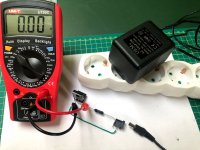
Anyway, my simple setup is in the picture:
- PS wallwart is rated 12V 800mA though in reality is gives about 14.10-14.40 V under the load. I also understand that the other day this could be different as it not regulated.
- resistor is 60 ohm, 1%, 3W (gets quite hot under ~2W load).
Measured just two MOSFETs yet. Got 4.01 and 4.02 Vgs after 30 seconds.
If I keep it longer, I see Vgs falling down to 3.98V in 1 min., 3.97 in 2 min., 3.96 in 3 min.
MOSFET itself gets just a little tiny warm in 3 min. (running at about 170mA Id).
Does all this makes any sense (without any thermal measurement/control)?
How long should I wait before taking the Vgs measurement?
Or is all this just monkey business?
Trying to match transistors for the first time, so any teaching would be appretiated.
Thanks.
- Alvis
Attachments
Looks interesting..
I think the circuit needs more room to breathe, allow possibility for setting different Vds load lines.
So at least +/– 24V on the power rails, maybe 30.
hardly game changer
Should the DC wires from the power supply to the amp board be twisted together ?
Will it make a difference ?
Or is the shortest path/length better ?
Short answer: yes, yes, no.
Long answer:
http://hifisonix.com/wordpress/wp-content/uploads/2018/07/Amplifier-PCB-Design-Guidlines-for-Minimizing-Hum-1-1.pdf
http://hifisonix.com/wordpress/wp-content/uploads/2019/02/Ground-Loops.pdf
Alvis,
What you're seeing sense.
The main thing is keep your mosfets at the condition when you start, and do
your measurement at a consistent time. (I would go no less than one minute.)
You're not looking for absolute measurements, only to help you select pairs
that are reasonably close.
Cheers,
Dennis
What you're seeing sense.
The main thing is keep your mosfets at the condition when you start, and do
your measurement at a consistent time. (I would go no less than one minute.)
You're not looking for absolute measurements, only to help you select pairs
that are reasonably close.
Cheers,
Dennis
Thanks, Dennis!
Checked all 25. Measured Vgs after 3 minutes.
18 fell into 3.96-3.97, 6 into 3.93-3.95, and one was at 4.00 Vgs.
Do numbers in the circles in the corners of the case have something in common with the batch number? In my tube I had several "series" like 01 08, 02 08, ... 08 08, then 01 12, 02 12, ... 10 12, and 05 01, 05 02, ... 05 05, and that one with 4.00 Vgs was 12 04.
Overall, Extreme_Boky was right when he suggested I will find plenty of pairs from the whole tube. Thanks, Boky. (Though Mouser did not guarantee that they all be from the same batch, and they were not exactly from one batch as I understand).
Anyway, two small questions remain - will they behave the same at 800mV in Aleph J as they behaved at 170mV in my test? I think I will have to check that in the circuit 🙂
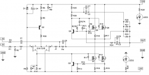
And when speaking about the matched pairs, do I understand correctly that the pairs are Q5-Q6 and Q7-Q8 (schematics attached for the quick look)?
Thanks to everyone! That was an interesting experience for me (though the process itself was quite boring 🙂)
Checked all 25. Measured Vgs after 3 minutes.
18 fell into 3.96-3.97, 6 into 3.93-3.95, and one was at 4.00 Vgs.
Do numbers in the circles in the corners of the case have something in common with the batch number? In my tube I had several "series" like 01 08, 02 08, ... 08 08, then 01 12, 02 12, ... 10 12, and 05 01, 05 02, ... 05 05, and that one with 4.00 Vgs was 12 04.
Overall, Extreme_Boky was right when he suggested I will find plenty of pairs from the whole tube. Thanks, Boky. (Though Mouser did not guarantee that they all be from the same batch, and they were not exactly from one batch as I understand).
Anyway, two small questions remain - will they behave the same at 800mV in Aleph J as they behaved at 170mV in my test? I think I will have to check that in the circuit 🙂
And when speaking about the matched pairs, do I understand correctly that the pairs are Q5-Q6 and Q7-Q8 (schematics attached for the quick look)?
Thanks to everyone! That was an interesting experience for me (though the process itself was quite boring 🙂)
Attachments
What wire gauge did you use for speakers output and PSU? 16 or 14 AWG?
Thanks
I used 16 gauge wire for PSU and outputs to speakers.. Not for any reason other than it was the thickest wire I had on hand..
avitkauskas, what are you using to hold the MOSFETs?
Thanks for the great photo of your test jig!
Thanks for the great photo of your test jig!

Thanks, Dennis!
Checked all 25. Measured Vgs after 3 minutes.
18 fell into 3.96-3.97, 6 into 3.93-3.95, and one was at 4.00 Vgs.
Do numbers in the circles in the corners of the case have something in common with the batch number? In my tube I had several "series" like 01 08, 02 08, ... 08 08, then 01 12, 02 12, ... 10 12, and 05 01, 05 02, ... 05 05, and that one with 4.00 Vgs was 12 04.
Overall, Extreme_Boky was right when he suggested I will find plenty of pairs from the whole tube. Thanks, Boky. (Though Mouser did not guarantee that they all be from the same batch, and they were not exactly from one batch as I understand).
Anyway, two small questions remain - will they behave the same at 800mV in Aleph J as they behaved at 170mV in my test? I think I will have to check that in the circuit 🙂
And when speaking about the matched pairs, do I understand correctly that the pairs are Q5-Q6 and Q7-Q8 (schematics attached for the quick look)?
Thanks to everyone! That was an interesting experience for me (though the process itself was quite boring 🙂)
I suppose that now you have a full appreciation of what I posted few pages back...
the heat dissipation at higher currents is a problem.... you need a temp. controlled environment, large heatsink.... the BEST is to try and do it... you'll understand 🙂
I think that the 2 groups of MOSFET's can be used without any issue, apart from that one that measured at 4.00Vgs.
The 2 groups are matched perfectly. The measured difference can be attributed to the multimeter reading/measurement tolerances, contact resistances and temperature variations.
This is exactly what I found when I checked my tube.
Last edited:
avitkauskas, what are you using to hold the MOSFETs?
Thanks for the great photo of your test jig!
I think that is a "Pin Header with Female Sockets".
avitkauskas, what are you using to hold the MOSFETs?
Thanks for the great photo of your test jig!
It's an Euroblock:
Mouser link
I suppose that now you have a full appreciation of what I posted few pages back...
I think that the 2 groups of MOSFET's can be used without any issue, apart from that one that measured at 4.00Vgs.
The 2 groups are matched perfectly. The measured difference can be attributed to the multimeter reading/measurement tolerances, contact resistances and temperature variations.
This is exactly what I found when I checked my tube.
Thanks, Boky! I always had the highest appretiation of your posts! 🙂
What I learned from this activity:
- Mouser do not guarantee the same batch even if you buy a full tube,
- Mosfets in a tube are still quite similar (except some - and that was good, I could see that my testing jig really gives different results in some cases 🙂)
- testing with low currents (up to 200mA or a bit more) is easy, with currents close to real usage (800mA or more) - difficult thermally.
Nice learnings! Thanks!
-Alvis
Setting up my bias and offset now and everything looks great !
Noticed that the discrete diodes in the power supply are quite warm at about 41deg C
Is that ok ?
Noticed that the discrete diodes in the power supply are quite warm at about 41deg C
Is that ok ?
Attachments
Last edited:
Carsten, thanks; I used your search term and came up with some useful connectors.
avitkauskas, thanks, I happened to order some slightly different terminal blocks on my last Mouser order to try out for wire to PCB connections, and they work for your test jig too!
avitkauskas, thanks, I happened to order some slightly different terminal blocks on my last Mouser order to try out for wire to PCB connections, and they work for your test jig too!
- Home
- Amplifiers
- Pass Labs
- Aleph J illustrated build guide