Hi, again. Got the boards today, now thinking through the parts buy.
On a recent Whammy build (my third), I splurged for Jantzen Superior Z-Caps for the input coupling capacitors. (Only about $20 extra, actually, so not a huge splurge.) It took some massaging to get them in place, but it did seem to me that they made a positive difference.
Any thoughts about how critical the input coupling caps are here? There is some room on the board, it seems.
SL15 47003
I am not an expert though. So take it for what it's worth.[/QUOTE]
Nice one, thanks so much
I am not an expert though. So take it for what it's worth.[/QUOTE]
Nice one, thanks so much
I second that matching source resistors is important, especially if you are using +/- 5% resistors.
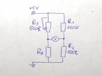
Have a look at my technique of matching source resistors. The usual multimeters and measurement techniques are very bad at measuring low resistances, but are quite accurate in measuring tiny voltages 😀
I also measured 10 Panasonic 0.47ohm 5% 3W resistors that I had in my stock.
I used the method attached here to do that. Choose R1 and R2 to be precisely 100K and 100R so that the difference is exactly 1000 times. Then tune the variable resistor so that you have exactly 0.00V on the voltmeter. Measure the resistance of R3 and Rx will be R3/1000.
I was glad to see that these Panasonic resistors, while rated at 5%, all fell into the region of 0.465-0.470 (1% from nominal 0.47), except one that was 0.475.
Also, as I am going to change the MOSFETS in my Aleph J, I de-soldered all of them and also measured their Vgs at Id of 170mA. These were MOSFETS bought from the diyAudio store and 4 of them had to be perfectly fine while the other 4 could be exposed to some high temperature close to 150C for about 20 min. or so (that's why I want to change them, as I measure too big THD in this channel). My measured Vgs of them were in the rage of 3.68-3.76 - that is in 0.08V (and that is ok if you have in mind that Papa says matching them to 0.1V is good enough). And these measurements corresponded precisely with the voltages I saw on their power resistors (variying from 395mV to 440mV exactly in these pairs that had the worst matching). This is assuming that the resistors themselves matches quite well (conclusion drawn from my measuremet of the new/unused yet resistors, as I could not do that for those on the boards already).
Yet at the same time I understood that it's quite easy to match MOSFETS yourself to 0.01V from the full tube of 25 for the same total cost. Also an interesting finding for me.
This is just a speculation from this short experience. I will post my bias voltages when I have MOSFETS replaced. It will be interesting to see if they match better.
And if this will bring the THD to the normal level...
Attachments
I ordered a stack/ clip of mosfets 25? Apparently manufactured consecutively from Mouser? and am very happy with results in the final product. Didn’t measure them.
The Aleph J and Crites B speakers are my most used set up now for many months. The F5 is taking a nap🙂
The Aleph J and Crites B speakers are my most used set up now for many months. The F5 is taking a nap🙂
Been listening to my AJ. Love it. Very listenable. Lots of details, especially in the mids and very easy on the ears. Very apparent when I listened to The Notting Hillbillies. The only area where it misses out against my KSA50 is the bass drive and dynamics, which I can hear when I played Level 42's The Pursuit Of Accidents.
Definitely worth the while to build and lovers of Country and Jazz will love it to bits.
Also would note that it might sound better on other speakers. My B&W Matrix 1 speakers are notorious for wanting lots of current to sound their best.
Definitely worth the while to build and lovers of Country and Jazz will love it to bits.
Also would note that it might sound better on other speakers. My B&W Matrix 1 speakers are notorious for wanting lots of current to sound their best.
Last edited:
Mine sounds amazing on my '86 Klipsch Heresy IIs. I've never heard them sound so good. Of course, it's so revealing that it really finds that sore spot around 8K that HF horn throws out there when certain female vocalists are performing. 😛
It really is a brilliant amplifier, especially with Jazz and Blues and any kind of acoustic music. And Mark Knopfler 😀. And Pink Floyd. And...
It really is a brilliant amplifier, especially with Jazz and Blues and any kind of acoustic music. And Mark Knopfler 😀. And Pink Floyd. And...
Been listening to my AJ. Love it. Very listenable. Lots of details, especially in the mids and very easy on the ears. Very apparent when I listened to The Notting Hillbillies. The only area where it misses out against my KSA50 is the bass drive and dynamics, which I can hear when I played Level 42's The Pursuit Of Accidents.
Definitely worth the while to build and lovers of Country and Jazz will love it to bits.
Also would note that it might sound better on other speakers. My B&W Matrix 1 speakers are notorious for wanting lots of current to sound their best.
Last edited:
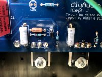
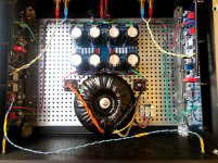
Ripped my Aleph J apart: rewired mains to go under the bottom plate, changed all MOSFETS, put everything back and have good news and bad news.
Good news first. My MOSFETS matching worked perfectly and my new ones are matched much closer that the ones from the store. Hurrah!
I easily set the bias and the voltages on the source resistors are:
.399, .401, .401, .403 left
.398, .400, .405, .391 right
(small mismatch on the last two, perhaps resistor difference as I did not change them)
Output offset is also stable near 0.0V with the inputs shorted.
But... the bad news is that both channels are very noisy and show a lot of THD and intermodulation when measuring on REW with Focusrite.
I am in my 50s, but only about 1 year in this hobby. During this year I buit quite a few amps from the kits and also 3 First Watt clones (you can see this in my signature line). All of them worked from the first power up without any problems. But not Aleph. Aleph is playing some dirty tricks on me (I know, she wants me to learn...)
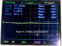
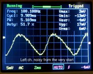
Interesting thing is that my right channel was working kind of good after the initial build, but you probably remember that I failed with the thermal pads and therefore had my left channel run a bit too hot for some short time. Right channel temperatures were not so bad, so I suspected only the left channel. And this showed up when doing measurements (I posted that before: left channel very bad, right - ok with THD about 0.06%). Now, when I changed all MOSFETS (left channel because they were suspected to be scorched, righ channel because I expected, rightly, that my new MOSFETS are better matched), initially left channel did show high noise (I was listening with the headphones connected to the amp output), and the right channel seemed perfect (no noise whatsoever!). I also tried to see what I have on the outputs with the oscilograph (a toy one, handheld DSO Shell) and this confirmed the big difference.
Though, when I set it up everything for the REW measurements, my right channel showed the same bad behaviour as the left! And then I also started to hear big noise in the headphones on the right channel too!
Another symptom was that output offset was very stable on arround 0.0V on the right channel initially (after the warm up) and it did not matter for this channel if the inputs are shorted or not, but the left channel was fine with the input shorted, but jumped to -50mV immediatelly when the input was opened (same behaviour I had after my initial build with the store MOSFETS). Strange thing is that now, when the right channel became bad too, the same effect has a place on it: offset changes to about -50mV when input in open.
My head goes dizzy, I can follow the instructions and can solder, but I am too newb yet to understand the schematics properly and troubleshoot. I have a feeling that there is something systemically bad in my build that broke the left channel immediatelly but was ok for some time on the right channel, until it manifested there as well. And its not the MOSFETS, now I can be sure about that. And it's not my measuring equipment (REW software and Focusrite) as I immediatelly tested my F5 with the same setup and got nice and good results. And the buzz on the speakers with Aleph J is really bad also.
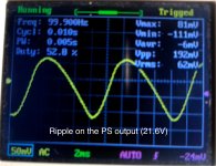
I rechecked all the parts. Looks good and correct. Could I mess somethig up with all the options with the jumpers instead of the resistors that Aleph has? I can list all my choices of jumpers if that would help to understand the problem. Or is it my PSU? I see ripple of 192 mVpp on the PSU output (rails voltage is + and - 21.6 V under load). I used same PSU parts as on F5 amp, capacitors are 18.000uF x 8.
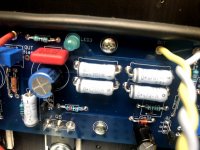
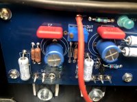
I also attach a lot of pictures as they say more than words.
Could anyone be so kind to guide me though this dark Mirkwood forest?
Good news first. My MOSFETS matching worked perfectly and my new ones are matched much closer that the ones from the store. Hurrah!
I easily set the bias and the voltages on the source resistors are:
.399, .401, .401, .403 left
.398, .400, .405, .391 right
(small mismatch on the last two, perhaps resistor difference as I did not change them)
Output offset is also stable near 0.0V with the inputs shorted.
But... the bad news is that both channels are very noisy and show a lot of THD and intermodulation when measuring on REW with Focusrite.
I am in my 50s, but only about 1 year in this hobby. During this year I buit quite a few amps from the kits and also 3 First Watt clones (you can see this in my signature line). All of them worked from the first power up without any problems. But not Aleph. Aleph is playing some dirty tricks on me (I know, she wants me to learn...)
Interesting thing is that my right channel was working kind of good after the initial build, but you probably remember that I failed with the thermal pads and therefore had my left channel run a bit too hot for some short time. Right channel temperatures were not so bad, so I suspected only the left channel. And this showed up when doing measurements (I posted that before: left channel very bad, right - ok with THD about 0.06%). Now, when I changed all MOSFETS (left channel because they were suspected to be scorched, righ channel because I expected, rightly, that my new MOSFETS are better matched), initially left channel did show high noise (I was listening with the headphones connected to the amp output), and the right channel seemed perfect (no noise whatsoever!). I also tried to see what I have on the outputs with the oscilograph (a toy one, handheld DSO Shell) and this confirmed the big difference.
Though, when I set it up everything for the REW measurements, my right channel showed the same bad behaviour as the left! And then I also started to hear big noise in the headphones on the right channel too!
Another symptom was that output offset was very stable on arround 0.0V on the right channel initially (after the warm up) and it did not matter for this channel if the inputs are shorted or not, but the left channel was fine with the input shorted, but jumped to -50mV immediatelly when the input was opened (same behaviour I had after my initial build with the store MOSFETS). Strange thing is that now, when the right channel became bad too, the same effect has a place on it: offset changes to about -50mV when input in open.
My head goes dizzy, I can follow the instructions and can solder, but I am too newb yet to understand the schematics properly and troubleshoot. I have a feeling that there is something systemically bad in my build that broke the left channel immediatelly but was ok for some time on the right channel, until it manifested there as well. And its not the MOSFETS, now I can be sure about that. And it's not my measuring equipment (REW software and Focusrite) as I immediatelly tested my F5 with the same setup and got nice and good results. And the buzz on the speakers with Aleph J is really bad also.
I rechecked all the parts. Looks good and correct. Could I mess somethig up with all the options with the jumpers instead of the resistors that Aleph has? I can list all my choices of jumpers if that would help to understand the problem. Or is it my PSU? I see ripple of 192 mVpp on the PSU output (rails voltage is + and - 21.6 V under load). I used same PSU parts as on F5 amp, capacitors are 18.000uF x 8.
I also attach a lot of pictures as they say more than words.
Could anyone be so kind to guide me though this dark Mirkwood forest?
Attachments
-
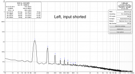 L input shorted.png117.5 KB · Views: 128
 -
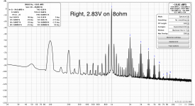 R.png174.3 KB · Views: 142
 -
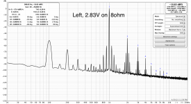 L.png163.6 KB · Views: 148
 -
 IMG_2513.jpg724.1 KB · Views: 141
 -
 IMG_2512.jpg860.7 KB · Views: 162
 -
 IMG_2511.jpg603.5 KB · Views: 150
 -
 IMG_2516.jpg840.7 KB · Views: 242
 -
 IMG_2515.jpg693.7 KB · Views: 237
 -
 IMG_2514.jpg688.4 KB · Views: 246
 -
 IMG_2517.jpg809 KB · Views: 244
I had the same problem with my aleph. One channel became noisy after one month of beautiful sound. Output offset was jumping about +-50mV.
I had checked every resistor and all MOSFETs, and everything was good.
The only way for me was to change the JFets in faulty channel. And it solved the task.
Good luck.
I had checked every resistor and all MOSFETs, and everything was good.
The only way for me was to change the JFets in faulty channel. And it solved the task.
Good luck.
Thanks, @dabochkarev. This is something I was expecting. Nice to see that the symptoms were the same, so there is a good chance that this is the fault and I will have to learn how to match JFETs now 🙂
But then the question is: why this happens? Do these JFETs run at some limit? Is something in schematics that has to be changed that the same problem would not reoccur later? Perhaps there is something that stresses JFETs too much for some reason?
I'm very thankful for that suggestion.
Do others have any other insights?
-Alvis
Last edited:
Looking at the BOM comments now:
Note 3
Add gate stopper resistors in the place of the jumpers if required to combat parasitic oscillations and improve stability.
This is instead of the J1 and J2.
I also have a jumper in the place of R30.
R6 is also a jumper and R8 is a fixed 1K resistor.
Can this be a parasitic oscillation? Can it be that Jfets are ok, but they need some gate resistance added?
Last edited:
The spectrum looks like an AM signal. 1Khz modulated with 100Hz. (Carrier with lsb and usb signals). Something wrong with feedback loop?
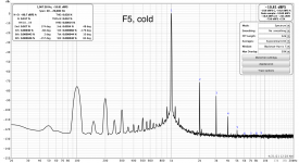
Hm.. Trying to understand my problems, I made LTSpice models of Aleph J and F5 with all the components set to my real values (set trimpots so that bias voltage would be 400mV and output DC close to 0).
And what I see in simulated FFT makes me wonder.
Look at the simulated FFT of Aleph J and F5 and compare them with my real measuments with REW and Focusrite. Do the simulations seem to match the real results? Does that mean that my Aleph J works "as designed" and the same problem shows in the simulation? If yes, where did I failed with components (looks like I was following the BOM)? Putting 100R in place of J1 and J2 and R30 in the simulation did not make any difference.
I'm new to all this. Does it all make sense? Help please!
Attachments
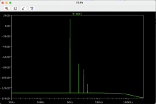

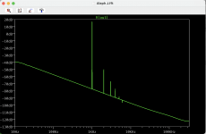
@henryve, if you ask about Aleph J - I don't know and want to find out. Levels of 100Hz and 1kHz harmonics are very much increased there. Concerning F5 - it's actually fine, it is barely audible even on quite sensitive Klipschs.
My recommendation is to replace j74's with j103's, for example , adjust bias and offset before placing order for JFETS.
Thanks for the suggestion, Dmitriy.
But what is the logic behind that? Why LSJ74's are not good where they were planned to be good and why 2SJ103 is better and should work? I'd love to learn in the processes and understand the reasoning.
Also, 2SJ103 is out of production, as I understand, so getting them from eBay involves some risk of counterfeit, I suppose.
FYI, this is what I measured at full power output into 8R.
Measurements at 14V RMS (24W)
100Hz 0.056 THD
500Hz 0.25 THD
1KHz 0.38 THD
10KHz 4% THD
20KHz 8% THD
Measurements at 14V RMS (24W)
100Hz 0.056 THD
500Hz 0.25 THD
1KHz 0.38 THD
10KHz 4% THD
20KHz 8% THD
Eddy, is that from the simulation? How do you calculate THD in the simulation?
I wonder why the simulation shows this slope up towards the low frequencies in AJ, but not in F5.
EDIT: I probably got it: you can see THD is in the .log file. But what does these THDs say to us?
I wonder why the simulation shows this slope up towards the low frequencies in AJ, but not in F5.
EDIT: I probably got it: you can see THD is in the .log file. But what does these THDs say to us?
Last edited:
- Home
- Amplifiers
- Pass Labs
- Aleph J illustrated build guide