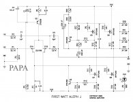
1.tiny on input only
2.good , slow blow
3.fuse holder for plate montage
4.put nail size fuse inside IEC, proper one later
for small details , see pics at SissySIT, another one | Zen Mod Blog
2.good , slow blow
3.fuse holder for plate montage
4.put nail size fuse inside IEC, proper one later
for small details , see pics at SissySIT, another one | Zen Mod Blog
1.tiny on input only
2.good , slow blow
3.fuse holder for plate montage
4.put nail size fuse inside IEC, proper one later
for small details , see pics at SissySIT, another one | Zen Mod Blog
Thanks, ZM!
What do you mean by "nail size fuse"?
I found myself trying to put together AJ on A30 board just for fun. I took many hours examining and cross referencing official A30 schematic with AJ schematic and think I have taken the necessary modifications so here is where the fun begins.
Because this is an experiment, I took old ZTX450/550 and J74 that I had removed from old projects and tested in $10 tester. Everything seems ok. IRFP240 are used as well.
I fired it up and see a nice 8.3V across R8 but only 3.43V across R7 and across the CCS according to this schematic:

No warm glow from the source resistors and mosfets yet. I have 2K pot in R7 and 100K pot in R27. With R27 at full resistance, I see a few millivolts across source resistors and since I have R27 installed with socket pin headers, once I left the pot out and turned it on and it started to warm up but I wasn't reading voltages and turned it off before I let out any magic smoke. Does it sound like everything is still working and anything I should check/adjust? Right now I have 1K resistor in R8. 2K pot in R7 initially set at 1K and I can adjust down any offset to 0.00mV easily.
Suggestions? Worst case I'll put small mosfets in place of jfets and call it A30.
Because this is an experiment, I took old ZTX450/550 and J74 that I had removed from old projects and tested in $10 tester. Everything seems ok. IRFP240 are used as well.
I fired it up and see a nice 8.3V across R8 but only 3.43V across R7 and across the CCS according to this schematic:

No warm glow from the source resistors and mosfets yet. I have 2K pot in R7 and 100K pot in R27. With R27 at full resistance, I see a few millivolts across source resistors and since I have R27 installed with socket pin headers, once I left the pot out and turned it on and it started to warm up but I wasn't reading voltages and turned it off before I let out any magic smoke. Does it sound like everything is still working and anything I should check/adjust? Right now I have 1K resistor in R8. 2K pot in R7 initially set at 1K and I can adjust down any offset to 0.00mV easily.
Suggestions? Worst case I'll put small mosfets in place of jfets and call it A30.
I have not installed C4 (10uF across 9.1V zener) yet if it makes a difference. It doesn't make any difference temporarily but I will install it if this thing works. What is the purpose of C4?
Zeners are noisy... C4 is there to couple the noise from the B2 base, to its "virtual ground return", which in this case, for Q2 -> is the V+ rail.
JFET's are sensitive to static discharge. You HAVE to use an antistatic wrist band correctly connected to a ground potential whilst handling the little buggers. My bet is that you damaged the JFET's... the output MOSFET's will not start conducting properly unless the voltage drop across R7 is at least 4.3V... so, the current through the Q1A is not sufficient at the moment to generate a required voltage drop; hence my diagnostics re: damaged JFET's.
JFET's are sensitive to static discharge. You HAVE to use an antistatic wrist band correctly connected to a ground potential whilst handling the little buggers. My bet is that you damaged the JFET's... the output MOSFET's will not start conducting properly unless the voltage drop across R7 is at least 4.3V... so, the current through the Q1A is not sufficient at the moment to generate a required voltage drop; hence my diagnostics re: damaged JFET's.
Thanks for that information! Yes, that would be 4.77A per rail on startup, more than I expected! I plan to do first power on at a lower voltage, something like +/- 15V then raise the voltage once everything looking ok (no smoke).
Based on the voltage drop figures provided on the Aleph J schematics, across R8 and R7, plus a bit of voltage drop across Q2 (and a very little drop across Q1A), + and - 15 V DC at around 5 amps should be enough...but only just!
You can invest in a variac... and tone generator + an oscilloscope. Then with a tone generator outputting 2V at 1KHz sinewave, you can monitor the symmetry at the amplifier output; the amplified sinewave, while increasing the AC slowly... you also do not want to see any oscillations. The output sinewave should slowly increase as you crank the mains voltage - the same behaviour as increasing the volume. This ensures no explosions/unpleasantries 🙂, sanity and long and prosperous life.
Swapped out the J74 pair, soldered in pin headers and tried fresh jfets but the result is still the same - 3.6V across R7 and across the CCS.
Are the JFET's from the appropriate grade (BL)?
The current through that R7 is not large enough... this should help you fault-find...
The current through that R7 is not large enough... this should help you fault-find...
Thanks for the information Extreme_Boky, it is helpful.
The board is Peter Daniel's A30 board:
The Aleph30 PCB layout
This is designed for IRF610 and 9610 front end and there are a few small trace differences because the A30 schematic is different. The conversion mapping I figured out and entered into an excel sheet
View attachment AJ on A30 board.pdf
The board is Peter Daniel's A30 board:
The Aleph30 PCB layout
This is designed for IRF610 and 9610 front end and there are a few small trace differences because the A30 schematic is different. The conversion mapping I figured out and entered into an excel sheet
View attachment AJ on A30 board.pdf
I realize the pinout is different from the small mosfets and the jfets and did a creative 'twist' to get the legs in the right spots but managed it without twisting legs around each other. Take the source leg and push it across to the opposite source (sources are tied together so it is ok), offset the G and D by 1 spot and do the same for the other side. It works and no ugly mangled jfets.
Good morning to you all.
Could you give me the ANTEK reference for the 2X 18V 400 VA transformer because the one I use does 300 VA and it heats up a bit in my opinion.
Thank you in advance.
Could you give me the ANTEK reference for the 2X 18V 400 VA transformer because the one I use does 300 VA and it heats up a bit in my opinion.
Thank you in advance.
Have you checked ANTEK website for the shipping costs to France? When I tried to ship ANTEK to Australia, I was horrified... shipping costs were insane.
Why not use Toroidy; they are based in Poland, fully potted and shielded. You can also get a very nice mounting plate that will make assembly task a breeze.
Why not use Toroidy; they are based in Poland, fully potted and shielded. You can also get a very nice mounting plate that will make assembly task a breeze.
after few hours of work , if you can put your fingers on Donut (be careful not to touch everything with exposed mains voltage !) and keep them for good , Donut is good
bit is normal ....... plenty isn't
say that 50C (closed case) is OK in my book ........ even if Donuts I'm using are much colder (1 of 250VA per channel)
bit is normal ....... plenty isn't
say that 50C (closed case) is OK in my book ........ even if Donuts I'm using are much colder (1 of 250VA per channel)
Have you checked ANTEK website for the shipping costs to France? When I tried to ship ANTEK to Australia, I was horrified... shipping costs were insane.
Why not use Toroidy; they are based in Poland, fully potted and shielded. You can also get a very nice mounting plate that will make assembly task a breeze.
I’m in the states and order from toroidy. I really like their transformers. Nothing with antek though; they make fine transformers too
However, it seems no one has actually answered your original question... Great advice and information provided all around, but if you would still like an Antek...
AS-4218 - 400VA 18V Transformer - AnTek Products Corp
AS-4218 - 400VA 18V Transformer - AnTek Products Corp
toto34,
Link for a 400VA of the shelf transformer from within Europe:
RKD 400/2x18 | Block 115V ac, 230V ac, 2 x 18V ac Toroidal Transformer, 400VA 2 Output | RS Components
ItsAllInMYHead,
I clicked the Antek link out of curiosity, looks like the transformer is currently out of stock...
Link for a 400VA of the shelf transformer from within Europe:
RKD 400/2x18 | Block 115V ac, 230V ac, 2 x 18V ac Toroidal Transformer, 400VA 2 Output | RS Components
ItsAllInMYHead,
I clicked the Antek link out of curiosity, looks like the transformer is currently out of stock...
Last edited:
- Home
- Amplifiers
- Pass Labs
- Aleph J illustrated build guide
