Aside from the bias being really high because the amp is out of balance, (due to the offset being close to the whole rail), not really.
It’s a very DC coupled amp and if something is out of whack because of a broken solder joint or similar, the readings are going to be all over the place. This is a somewhat common issue.
It’s a very DC coupled amp and if something is out of whack because of a broken solder joint or similar, the readings are going to be all over the place. This is a somewhat common issue.
Quick question about the mains hook up: what value is the capacitor that goes on the terminal block in between the two CL60s?
Disregard that last question (i think). Just found it on the PSU schematic, imagine that! C9 should be .0033 uf? And what should the voltage rating be? Would something like this work?
Last edited:
Aside from the bias being really high because the amp is out of balance, (due to the offset being close to the whole rail), not really.
It’s a very DC coupled amp and if something is out of whack because of a broken solder joint or similar, the readings are going to be all over the place. This is a somewhat common issue.
I'm going to take apart the left channel and re flow every solder joint, just to be sure I don't have a problem in the future. At least I know the general vicinity, R27, seems like every time I adjust with a screwdriver, the bias and offset go to 880mV and 18v.
I thought it was a bad pot, however, if I'm going in the amp and disassemble the channel, might as well replace the pot AND re flow all the joints nearby.
This was the issue I had when I first applied mains power to the amp, it took a couple of minutes and me adjusting R27 back and forth before bias and offset calmed down.
I wish I could say it is definitely the pot, however, I couldn't duplicate the issue by adjusting R27 all the time.
This was the issue I had when I first applied mains power to the amp, it took a couple of minutes and me adjusting R27 back and forth before bias and offset calmed down.
I wish I could say it is definitely the pot, however, I couldn't duplicate the issue by adjusting R27 all the time.
Thanks, 6L6! Glad I asked 😀
Elwood625's suggestion a few pages back of securing the mosfets with small heat sinks made sense to me - particularly in terms applying even pressure across the entire mosfet for better contact with the main heatsink. I didn't want to wait for heatsinks to be delivered though, so thought I'd just try large washers. Before I solder them, just want to check with the brain trust here: would there be any disadvantage or problem using the bigger washers that I'm not considering?
Attachments
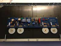
All you need are the "gold" colored washers, I'm concerned the silver colored ones may be to big in diameter and to close to the pins of the MOSFET. I've had power transistors arc to heat sinks/washers to close to pins.
All you need are the "gold" colored washers, I'm concerned the silver colored ones may be to big in diameter and to close to the pins of the MOSFET. I've had power transistors arc to heat sinks/washers to close to pins.
Thanks for the caution, elwood625. I guess for now I'll stick with the standard washers. I'm too eager to keep moving on the build! I suppose it would be pretty easy to add heatsinks or a slightly larger gold washer down the road without have to reflow the solder. Thanks!
Elwood625's suggestion a few pages back of securing the mosfets with small heat sinks made sense to me - particularly in terms applying even pressure across the entire mosfet for better contact with the main heatsink. I didn't want to wait for heatsinks to be delivered though, so thought I'd just try large washers. Before I solder them, just want to check with the brain trust here: would there be any disadvantage or problem using the bigger washers that I'm not considering?
The bigger washers are an advantage. The big washer applies even pressure over a large area of the mosfet against the heat sink. There is good for even flow of heat to the heat sink as you have mentioned.
The heat sink material may not be as thick as the washer so it may not be as good in distributing the clamping pressure.
A small or thin washer concentrates the clamping force of the screw over a smaller area of the mosfet, so the flow of heat is not as efficient.
Furthermore, the concentration of clamping force over a smaller area physically stresses the mosfet in flexure.
PS: As long as the washers are not so big that they are a problem as mentioned by Elwood625.
Last edited:
It must be a very small improvement. If it were a gigantic benefit, every power transistor bolted to a heatsink in every piece of electronics, everywhere in the world, would include washers. Every manufacturer of power semiconductors would enthusiastically & vigorously recommend washers in their datasheets, application notes, and development board literature.
But they don't.
But they don't.
I'd put my money in Belleville washers. If not properly torqued it's possible that neither the little nor the big washer will be doing anything after a bunch of heat cycles.
Bench supply current limit value
Hi all,
I will soon be powering up my boards/heatsink channels from a current limited bench supply. The question is what current value would you all suggest I set the current limit to? What is the typical current draw of these boards? My supply goes up to 5A, so I assume that is more than enough?
Hi all,
I will soon be powering up my boards/heatsink channels from a current limited bench supply. The question is what current value would you all suggest I set the current limit to? What is the typical current draw of these boards? My supply goes up to 5A, so I assume that is more than enough?
4A should be okay.... on a power-up first time, I had around 560mV across the 0.47ohm resistors, so that will require a full 5A source, for both channels. After adjustment, 4A should be ok. Do not be surprised if the bench PS starts smelling like lacquer burning...
I'd put my money in Belleville washers. If not properly torqued it's possible that neither the little nor the big washer will be doing anything after a bunch of heat cycles.
I haven't heard "Belleville washer" in decades, nice to hear the real name, here in the US, wavy washer. Every bolt should have a lock washer and then a flat washer for the lock washer to grip.
Don't forget anti-sieze compound on steel bolts threaded into alloy. Protects the threads from pulling and prevents corrosion between the different metals.
My two cents today.
4A should be okay.... on a power-up first time, I had around 560mV across the 0.47ohm resistors, so that will require a full 5A source, for both channels. After adjustment, 4A should be ok. Do not be surprised if the bench PS starts smelling like lacquer burning...
Thanks for that information! Yes, that would be 4.77A per rail on startup, more than I expected! I plan to do first power on at a lower voltage, something like +/- 15V then raise the voltage once everything looking ok (no smoke).
I have the Aleph boards and PSU boards populated, and beginning to plan my layout for dual mono. Have been reading back through this and other build threads. A few questions that have come up for which I haven't yet found answers:
1. Is input signal wire the only wire that should be of a small diameter? I assumed the instruction to "use small diameter wire for signal" meant both input and output, but in most photos I've seen, the signal output wire (PCB to speaker binding posts) is large diameter. What gauge wire do you recommend for the output signal?
2. Based on ZM's calculation I found a few pages back, the fuse should be rated according to dividing the transformer VA by the outlet voltage. Just want to confirm that in my case (400VA/120V = 3.3) I should use a 3.5amp fuse? Slow blow variety?
3. For those of you that have done dual mono builds, what are you using to hold the fuse after the IEC?
4. If I'm placing the fuse after the IEC, does this mean I should leave the fuse slot in the IEC empty?
Thanks. I'm sure I will have more questions as I progress to wiring, grounding, etc.
- Home
- Amplifiers
- Pass Labs
- Aleph J illustrated build guide