I know it's not easy to remove the PCB's from an amp, cut the trace, insert the 10-20ohm resistor, mount everything back... so, I remembered what I did to TEST if my suggestion is going to work first, before doing all the hard work. So, here it is🙂🙂:
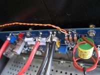
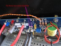
Check the attached photos. Quickly scroll between "Before" and "After"... and you'll get what I mean...
1. Unsolder both GND wires (one coming from the PS, the other coming from the speaker's negative binding post)
2. Tie them (solder them) together.
3. Leave them "floating in the air"
4. Solder the 10-ohm resistor to the end of these two wires.
5. Solder the other end of the resistor to GND on the PCB
Turn the amp on. The buzz will be gone (hopefully).
If it is not gone, look elsewhere for the root cause... remove the resistor, unsolder the wires, and then solder them back to the PCB.
Nick
Attachments
Of course, if the buzz is gone.... you can then choose between these two options:
Leave everything as-is and enjoy life.
or
Do it properly (remove amp PCB's, cut trace, place the resistor on the underside, put everything back...)
The side NOTE: Looking at the "After" photo.... isn't it obvious that the speaker return should NOT go to amp PCB??
Just sayin'...
Leave everything as-is and enjoy life.
or
Do it properly (remove amp PCB's, cut trace, place the resistor on the underside, put everything back...)
The side NOTE: Looking at the "After" photo.... isn't it obvious that the speaker return should NOT go to amp PCB??
Just sayin'...
well , if you make wires on that cap even longer, you can easily turn that thingie in AM Detector

The wires are gone now; they are very short now because I have firmly settled on that cap. I left them long in case I decided to sell those caps...
I am always enjoying your unrelated-to-anything comments, showing everyone how knowledgable you are.....in an attempt to bring others down.
I am always enjoying your unrelated-to-anything comments, showing everyone how knowledgable you are.....in an attempt to bring others down.
well, Boky .......... that's really Extreme.
please , take my apology , and be welcome on my ignore list .
please , take my apology , and be welcome on my ignore list .
I know it's not easy to remove the PCB's from an amp, cut the trace, insert the 10-20ohm resistor, mount everything back... so, I remembered what I did to TEST if my suggestion is going to work first, before doing all the hard work. So, here it is🙂🙂:
Check the attached photos. Quickly scroll between "Before" and "After"... and you'll get what I mean...
1. Unsolder both GND wires (one coming from the PS, the other coming from the speaker's negative binding post)
2. Tie them (solder them) together.
3. Leave them "floating in the air"
4. Solder the 10-ohm resistor to the end of these two wires.
5. Solder the other end of the resistor to GND on the PCB
Turn the amp on. The buzz will be gone (hopefully).
If it is not gone, look elsewhere for the root cause... remove the resistor, unsolder the wires, and then solder them back to the PCB.
Nick
I still don't understand the idea of splitting GND into speaker-GND and input-GND (see my earlier post).
I totally agree with your suggestion of looking for the root cause of the hum. However, blindly inserting resistors without understanding what's going on does not seem right.
So, I ask again: what is the background idea of splitting GND into two different GNDs with a resistor???
Ouch.
There are better ways of avoiding ground loops via mains / chassis / protective earth that do not mess with the audio signal connections.
Earthing (Grounding) Your Hi-Fi - Tricks and Techniques
Ouch.
There are better ways of avoiding ground loops via mains / chassis / protective earth that do not mess with the audio signal connections.
Earthing (Grounding) Your Hi-Fi - Tricks and Techniques
if you did not design it yourself; there is no shorter way to reach star topology than broken traces....
...the long way...is diyAudio 😀
Regarding the loop break 10 ohm resistor, I have found this resource to very helpful and clear, written by diyAudio member ilimzn.
Ground Loops
Ground Loops
Regarding the loop break 10 ohm resistor, I have found this resource to very helpful and clear, written by diyAudio member ilimzn.
Ground Loops
Completely unrelated... Great Avitar. RIP Neil Peart
Sorry I meant to post this link, it explains the 10-ohm loop break resistor
http://hifisonix.com/wordpress/wp-c...4/ilimzns-Excellent-Posts-on-Ground-Loops.pdf
http://hifisonix.com/wordpress/wp-c...4/ilimzns-Excellent-Posts-on-Ground-Loops.pdf
Last edited:
It is VERY related. Take a look at page 37. It says that its WRONG to insert the hum breaking resistor into the Audi GND connection.Completely unrelated...

It is VERY related. Take a look at page 37. It says that its WRONG to insert the hum breaking resistor into the Audi GND connection.
I believe my complete message has been misunderstood. My comment about his avatar (Neil Peart Drummer for Rush) was that which is “completely unrelated” to the discussion.
It would be real helpful to those that are new to the game, if those who really understand the Aleph J design were to post an "official" diagram of the end-to-end grounding scheme for the Aleph J. Or if one does exist, please point in that direction.
Thanks!
Thanks!
It would be real helpful to those that are new to the game, if those who really understand the Aleph J design were to post an "official" diagram of the end-to-end grounding scheme for the Aleph J. Or if one does exist, please point in that direction.
Thanks!
I have not used the diyAudio boards for my Alephs, so I don't know the details of the diyAudio boards. However, I don't think the Aleph J is different than other amps in terms of grounding.
It would be real helpful to those that are new to the game, if those who really understand the Aleph J design were to post an "official" diagram of the end-to-end grounding scheme for the Aleph J. Or if one does exist, please point in that direction.
Thanks!
Hi, JSA1971, yes RIP Neil Peart, one of my heroes who had such a positive influence on me and many others. He was so much more than a great drummer.
Hi quackers, I was exactly in your place, looking for the definitive best grounding scheme, but unfortunately, there is no such thing.
There are many different opinions about how to best ground an amplifier, with pluses and minuses for each, so no perfect right answer. See for example this thread.
How to wire up an Amplifier
I am following, for the most part, the sources I posted earlier today, mainly because they make sense to me. Other things that make sense to me about grounding and wiring in general for audio frequencies.
1. Use star grounding to minimize common impedance coupling.
2. Source and return current should be balanced (same but opposite) on a set of wires. Don't have one wire sharing two or more different currents. For example, I plan to use (still building my amp) two ground wires from the star point to the amp boards, one for each voltage leg (so 4 power wires total to each board).
3. Twist any balanced sets of wires together so the currents cancel best, and keep them away from other wires and metal to the best possible. Capacitive and/or magnetic coupling can occur if they are close to metal so there could be currents running through something unintended. I see pictures of units wired to look clean and pretty, which means wires are tucked under the chassis bottom, or strapped along the heat sink or zip-tied together. That all looks pretty no doubt, but electric fields don't care about prettiness. I expect my unit will be somewhat of an ugly duckling. Obviously people are happy with the way their "pretty" units sound so this is undoubtedly a second-order effect.
As I build my amp, I'll try to take detailed photos of how the wiring is done at each step as I progress. Looking at pictures of other built units on this thread it's often hard to see exactly where the wires are going.
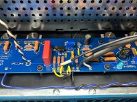
Didn't solve my hum issue...
Because you did not wire it correctly... you are feeding the dirty ground potential straight into -IN
The link between -IN and GND goes "too far", it should go to the GND eyelet CLOSEST to the -IN eyelet. This GND is a clean ground.
Last edited:
- Home
- Amplifiers
- Pass Labs
- Aleph J illustrated build guide