The bigger the more they will act as an antenna that picks up noise. I'd recommend to stay away for physically big caps if/where possible.
Maybe I should chose something smaller for С6, С7.
Still want C1 to be big axial cap.
Not rediculously big cap ofcourse.
This was motivation factor to learn new things like KiCad..
The film bypass capacitors (C6, C7 on your board) will be removed on the next revision of Store PCBs. They are not necessary.
I'd also add a second terminal blade near ground if people want to connect speaker - on the amplifier PCB. Sometimes it's quieter to do that.
That said, C1 should be film. Add a bunch of extra holes so people can use reasonable sized capacitors or big ones, as example here;
I'd also add a second terminal blade near ground if people want to connect speaker - on the amplifier PCB. Sometimes it's quieter to do that.
That said, C1 should be film. Add a bunch of extra holes so people can use reasonable sized capacitors or big ones, as example here;
Last edited:
Definitely will add GND terminal blade
And think what to do whith C6, C7.. get rid of or use something more compact.
Will gather info for now and start to make changes a bit later.
Thank you!
And think what to do whith C6, C7.. get rid of or use something more compact.
Will gather info for now and start to make changes a bit later.
Thank you!
The film bypass capacitors (C6, C7 on your board) will be removed on the next revision of Store PCBs. They are not necessary.
I'd also add a second terminal blade near ground if people want to connect speaker - on the amplifier PCB. Sometimes it's quieter to do that.
That said, C1 should be film. Add a bunch of extra holes so people can use reasonable sized capacitors or big ones, as example here;
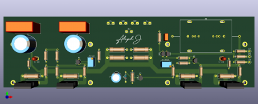
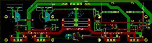
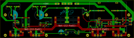
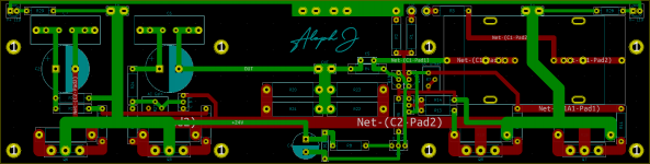
Some changes.
Small resistors up to RN60 size except LED risistors RN55 size.
C1 have 69.5mm lead space for big axial capacitor or 37.5mm 27.5mm 22.5mm 15mm for capacitors like FKP4 or regular MKP.
(Hole size for axial capacitor is 1mm because it was meant for specific cap with 0.8mm lead but can make it biger for versality)
C6,C7 stay. Lead space 22.5mm 15mm 5mm from FKP4 to small film caps.
Redraw silkscreen for some parts.
Q2, Q3, Q4 now ZTX/BC friendly with BCE marking.
Still only left channel board (74x260mm).
Will start to draw right channel when layout for left channel settle.
Already made change for Q2 E layout line after this scheenshots.. 😱
Still could be errors I can't see right now.
Like would LED's light connected that way.
Attachments
The line to the gate of q1a is quite long, maybe put an optional gate stopper resistor close to the gate?
And a question, the silkscreen text ‘Aleph J’, is it a Kicad font? Would be a nice engraving this nice font on the frontplate.
And a question, the silkscreen text ‘Aleph J’, is it a Kicad font? Would be a nice engraving this nice font on the frontplate.
Not sure. But could be done about 2cm closer.
Silk screen for Aleph J is not KiCad font.
I convert it to silk screen symbol in KiCad from screenshot I made of what I type in MS Word using a real font.. 😀
Font name is "The Doctor".
I also plan to make it as a copper pad without mask later.
Should look cool with ENIG and kind of meh with HASL.
Silk screen for Aleph J is not KiCad font.
I convert it to silk screen symbol in KiCad from screenshot I made of what I type in MS Word using a real font.. 😀
Font name is "The Doctor".
I also plan to make it as a copper pad without mask later.
Should look cool with ENIG and kind of meh with HASL.
Attachments
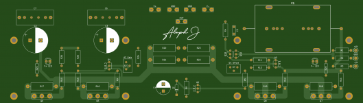
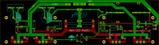
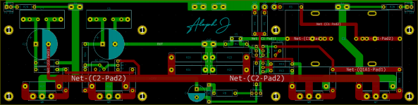
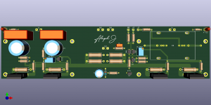
I gave up to make it as left and right pcb's and copycat inputs location from Didiet layout.
It went much beter and could be used as one board for both channels.
Board also decreased in size to 250mm x 74mm.
It went much beter and could be used as one board for both channels.
Board also decreased in size to 250mm x 74mm.
Attachments

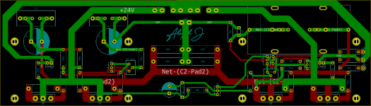
Try to optimize the part placement for shorter tracks. e.g.
Rotate 180 R25, put above r26
C2 asks to be next/rotated to r26
move r24 r27 and trans to the left, maybe rotate
move trans next to r14 r15?, and move them left
resistor? connected to r7 move left
the big cap is difficult, it asks to be in the top middle of the pcb, but it's big..
where possible copy high current tracks to other layer
...
Maybe add the "Algar" mods c102 c105, a few small caps, search the forum for info. I've made a smd aleph pcb version with these mods, because I could not get the original stable at full power and high freq.
Attachments

Thank you for a lot of valuable sugestions!
I have some ideas to make it more compact.
Will post what I got later.
I have some ideas to make it more compact.
Will post what I got later.
Halo guys,
I have built few Alephs in the past but have had some brake from DIY. I have bought a set of PCBs from DIY Audio store for AJ. Just to double confirm, the schematics from the beginning of the post use pots for bias, offset etc.. but I just want to build it as original and have it at hand as one of the amps I use depending on the speakers, can I simply use this schematics? I would use pairs of J74s 7-8mA matched. Obviously IRFP240 matched also. I mainly mean the resistors values, is it actual valid schematic of original?

Thanks in advance
I have built few Alephs in the past but have had some brake from DIY. I have bought a set of PCBs from DIY Audio store for AJ. Just to double confirm, the schematics from the beginning of the post use pots for bias, offset etc.. but I just want to build it as original and have it at hand as one of the amps I use depending on the speakers, can I simply use this schematics? I would use pairs of J74s 7-8mA matched. Obviously IRFP240 matched also. I mainly mean the resistors values, is it actual valid schematic of original?
Thanks in advance
Last edited:
Yes. Of course.
EDIT: I would suggest one change, you really want a 2K pot at R7 to adjust DC offset.
EDIT: I would suggest one change, you really want a 2K pot at R7 to adjust DC offset.
Last edited:
Many thanks! I just edited my question, that I mainly mean resistors values if they are correct as I'm just making the list to order Dale RN60D from Mauser.
And also out of couriosity, maybe this question has been asked already I saw in 6moons review the picture of original, some of the resistors are brown Dale, but part are some blue metal film, any reason for that?
I had been living with my own made Aleph 3 for quite few years in the past so hope building AJ will not be a problem for me.
Many thanks, and thanks for the tip with R7.
Last edited:
Those are some good looking boards. It's good to have options for us semi-obsessive DIY builders. 😉
Thank you! 🙂
Small changes possible but I am mostly happy how it went right now.
Need to calm down and relook it with a fresh eyes later.
Small changes possible but I am mostly happy how it went right now.
Need to calm down and relook it with a fresh eyes later.
Halo guys,
I have built few Alephs in the past but have had some brake from DIY. I have bought a set of PCBs from DIY Audio store for AJ. Just to double confirm, the schematics from the beginning of the post use pots for bias, offset etc.. but I just want to build it as original and have it at hand as one of the amps I use depending on the speakers, can I simply use this schematics? I would use pairs of J74s 7-8mA matched. Obviously IRFP240 matched also. I mainly mean the resistors values, is it actual valid schematic of original?
https://imageshack.com/i/pn8qXosNp
Thanks in advance
Yes. The bias will be around 1.25A per each "leg" and you will not be able to change it.
Also, match the R16-R19 in addition to matching the MOSFETs
The DC offset may not be a bang-on zero...
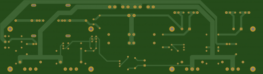
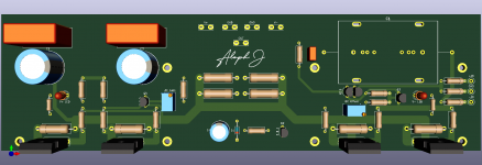
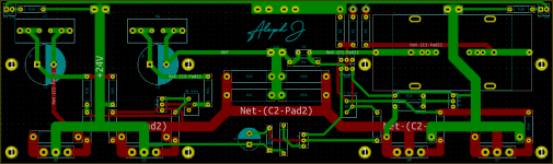
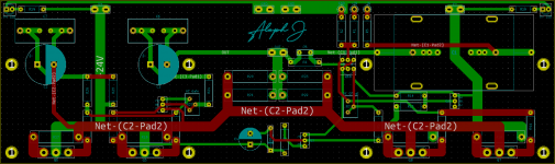
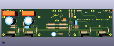
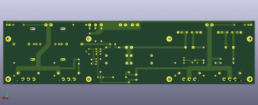
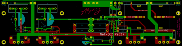
Yet another revision.
Small changes in traces, pads, a bit of footprints edit, some parts moved etc.
A place for wire jumper added in case only ubalanced (RCA) output will be used.
Lead space for jumper is 5mm
Inputs holes size is 1.2mm
I don't think someone would want to use thicker wire.
But some use coaxial cable and outer braid shield will go to.. hmmm.. GND?
Anyway all input pads have 1.2mm hole size.
"Aleph J" symbol as a copper pad now which I expect to be pretty with ENIG finish.
Also added text "Circuit by Nelson Pass. Layout by bla bla bla".. 😀
Attachments

Generally, np uses blue Panasonic for the 3w resistors
Many thanks.
.... I saw in 6moons review the picture of original, some of the resistors are brown Dale, but part are some blue metal film, any reason for that?
- Home
- Amplifiers
- Pass Labs
- Aleph J for Universal Mounting Spec