.... however, accidents do happen, so I think it is really wise to keep that C1 as an idiot-proof, safety precautionary measure.
The non-inverting input does not have a capacitor, so there is sill a way for DC to get in there. If one were to avoid accidents, wouldn't it make sense to fully block any DC by adding a capacitor to the non-inverting input, too (i.e., set gain = 0 instead of gain = 1 at DC)?
entire amp is acting as operational amplifier , and since negative feedback is connected from output to one ( that one with series cap) input , it'll behave as any other operational amp - it'll do with own output everything to level both inputs to have same potential ( DC voltage level)
if one input is coupled to outer world with cap , it'll see only own output in DC sense , while other input will see outer world
if you move DC coupled input by one volt DC (lousy DIY-ed preamp ) , all what amp needs to do is to move own output for one volt , so other input is seeing (being at) 1Volt and - voila! - both inputs are on same level
so , 1V on input causing 1V of change at output - that's unity gain ........... 1V/V , written differently
while for all other ziggyzaggy signals amp is still having gain of , say , 10 times , or 10V/V
edit: pretty much all Papamps , having symmetrical rails , and having cap or two at inputs are fully operational when idiotproof caps are shorted , for greatest purity and puritanism ........ while world is full with drek amps , which would go in flames , if you try the same
if one input is coupled to outer world with cap , it'll see only own output in DC sense , while other input will see outer world
if you move DC coupled input by one volt DC (lousy DIY-ed preamp ) , all what amp needs to do is to move own output for one volt , so other input is seeing (being at) 1Volt and - voila! - both inputs are on same level
so , 1V on input causing 1V of change at output - that's unity gain ........... 1V/V , written differently
while for all other ziggyzaggy signals amp is still having gain of , say , 10 times , or 10V/V
edit: pretty much all Papamps , having symmetrical rails , and having cap or two at inputs are fully operational when idiotproof caps are shorted , for greatest purity and puritanism
........ while world is full with drek amps , which would go in flames , if you try the same
Last edited:
Why would you feed DC into Alep J?
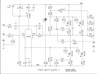
I have no intentions to do that. I am just trying to figure out the reasoning behind the way the the capacitor(s) are (not) implemented in the diyAudio schematic.
entire amp is acting as operational amplifier ... feedback is connected ... to level both inputs to have same potential ... if one input is coupled to outer world with cap , it'll see only own output in DC sense , while other input will see outer world ... if you move DC coupled input by one volt DC ... 1V on input causing 1V of change at output - that's unity gain...
Yup. That's exactly my point. If the goal is to avoid accidents with DC at the input, you'd want to avoid DC at the output. So you'd want gain = 0 at DC, not unity gain. The "avoid DC accidents" motivation would therefore lead to a capacitor in both inputs. That seems not to be the case here. Why?
He could get a cheap signal generator and oscilloscope and then see what happens gain-wise at different frequencies, with and without that C1 cap. I think that would be waaay less painful for everyone; this would help him understand the roll-off as well. He is asking a lot of question at Baybelfish thread as well.... It seems he could actually learn a lot by empirically proving all these explanations/suggestion he is getting from us.
He does have a signal generator and a scope. He has designed amplifiers before. He does understand the roll off idea. He is trying to understand why the DC blocking is incomplete with the diyAudio circuit of the Aleph J. He thinks that an explanation is not a proper explanation if it needs empirical poking around in the workshop. He does not like being called a he.
Last edited:
The post I deleted, and you quoted, actually is the best suggestion for you; you should definitely consider it. It will help you figure out the gain roll-off due to C1 position in the circuit, its value, and the JFET input impedance.
I deleted the post you quoted because, despite my best effort to help you (I even edited the original Aleph J circuit to show you what C1 actually does), you have never ever said "Thank you"... not even once. So, I decided to STOP helping you, and deleted the post.
I deleted the post you quoted because, despite my best effort to help you (I even edited the original Aleph J circuit to show you what C1 actually does), you have never ever said "Thank you"... not even once. So, I decided to STOP helping you, and deleted the post.
^Well, I will certainly have fun with the signal generator and scope once my Aleph J comes along, thanks.
However, the fun in the workshop will not answer my question "why does the diyAudio kit of the Aleph J not fully block DC at the input?". Someone has made the choice for unity gain at DC rather than zero gain at DC. As I explained above, I don't think that unity DC gain is a good protection for accidental DC at the input (zero DC gain would be the way to go). I therefore still wonder what the idea behind the unity DC gain is. It would be cool if someone could enlighten me.
However, the fun in the workshop will not answer my question "why does the diyAudio kit of the Aleph J not fully block DC at the input?". Someone has made the choice for unity gain at DC rather than zero gain at DC. As I explained above, I don't think that unity DC gain is a good protection for accidental DC at the input (zero DC gain would be the way to go). I therefore still wonder what the idea behind the unity DC gain is. It would be cool if someone could enlighten me.
my question "why does the diyAudio kit of the Aleph J not fully block DC at the input?".
Because that’s the way Nelson designed it.
https://www.diyaudio.com/forums/att...97d1194037871-aleph-schematic-aleph_j_sch-pdf
Tell me for a low-impedance load (speakers with an impedance of 3 ohms), are there any schematic changes? thanksBecause that’s the way Nelson designed it.
Attachments
Zen is correct, if you have a nasty inefficient load and like to listen at rock concert levels you may want to consider a bigger amp.
However, the Aleph isn’t bothered by hard to drive speakers, It will just happily play beautiful music at a little lower volume. There’s not a load that can hurt it. 🙂
However, the Aleph isn’t bothered by hard to drive speakers, It will just happily play beautiful music at a little lower volume. There’s not a load that can hurt it. 🙂
Zen is correct, if you have a nasty inefficient load and like to listen at rock concert levels you may want to consider a bigger amp.
However, the Aleph isn’t bothered by hard to drive speakers, It will just happily play beautiful music at a little lower volume. There’s not a load that can hurt it. 🙂
I am regularly surprised at how much drive AlephJ has! With BA3 front end, Smart TV source, Econowaves as my "home theatre" system it shakes the house with a movie with bass heavy sound track like Aquaman or the like.
The Econowaves JBL 2235H drivers in 5 cu ft cabs helps, but efficiency is mid-lower 90s dB. which is good but not fantastically efficient. AlephJ pushes them around like a super amp with juice to spare. Ditto M2, which is doing that duty right now. AlephJ in vinyl system at the moment.
Russellc
Last edited:
I am regularly surprised at how much drive AlephJ has! With BA3 front end, Smart TV source, Econowaves as my "home theatre" system it shakes the house with a movie with bass heavy sound track like Aquaman or the like.
The Econowaves JBL 2235H drivers in 5 cu ft cabs helps, but efficiency is mid-lower 90s dB. which is good but not fantastically efficient. AlephJ pushes them around like a super amp with juice to spare. Ditto M2, which is doing that duty right now. AlephJ in vinyl system at the moment.
Russellc
I can agree that the J pushes my speakers with much more authority than my M2. Why??? Can’t say. It’s obviously just a better match for my JBL’s. Plays louder, with much more effortless slam and pace than the M2. Its almost like it’s asking to be pushed harder if that makes sense. Both are great amps, I’m just always surprised by the J when it gets swapped back in to my system.
Zen is blef, if you have a nasty inefficient load and like to listen at rock concert levels you may want to consider a bigger amp.
However, the Aleph isn’t bothered by hard to drive speakers, It will just happily play beautiful music at a little lower volume.
I asked how to set the amplifier to a low impedance load. The HOOD1969 amplifier has this possibility, as the author, Mr. Leslie Hood, has pointed this out. Perhaps Maestro Pass knows the nuances of tuning the amplifier to a low-impedance load ?
The amplifier works without problems with a load resistance of 3 to 16 ohms. For maximum output power and minimum distortion, the values of several resistors and capacitors should be changed. The optimal ratings of resistors and capacitors for different load resistances are shown in Table 1:
An externally hosted image should be here but it was not working when we last tested it.
Resistors R1, R2 together with capacitor C1 form a stable current source. The quiescent current of the output stage operating in class A is changed by the selection of the ratio of resistors R1 and R2. The amplifier is sensitive to changes in load resistance and in order to get maximum output power and minimum distortion from it for speakers with a resistance of 4, 8 or 16 ohms, the values of the resistors R1 and R2 and the capacitor C1 should be different.
An externally hosted image should be here but it was not working when we last tested it.
Google Переводчик
Could someone confirm for me what is the latest revision for the Aleph J BOM?
I see Rev C on the site but it has a couple of inconsistencies with regarding the wrong lead spaced C6,C7 and also a 500ohm trimpot for R8. Have heard to just stick a 1K resistor or a 2K trimpot (as used in R7) into there instead...as what's shown in the schematic.
Also, it would be really beneficial if these BOM's were updated, so people like myself who trust the BOM's on the diyaudiostore website, don't go off and order the wrong stuff.
Have you seen this BOM? http://www.diyaudio.com/forums/atta...j-universal-mounting-spec-bom-aleph-j-ums.pdf It’s on the top of the 1st post of the guide.
There isn't a “latest revision BOM.” BOM with specific part numbers go stale because numbers change, suppliers change series, and not everybody can purchase from the same distribution channels.
Also, the passive parts make a very insignificant difference in the overall sound of these amplifiers. So use what you can get with no worries. The required information is on the schematic and the rest (leadspacings and sizes) can be determined with the PCB in hand.
That said, IF you want to make a BOM with current numbers from either Mouser or DigiKey, please send it to me and I’ll happily put in into the top of the first post.
To answer you specific questions, R8 just use 1K resistor and omit the pot. C6 C7, honestly, just leave them empty, but they do have 5mm lead spacing if you want to use them.
I saw that BOM yesterday when I was trying to figure out why something didnt fit and realized I didn't have the part that was specified. Then I saw the BOM on the diyaudio store site that listed the part I ordered, and all was clear.
So much to keep track of...so many parts not even needed. Is a 1k/.25w fine for R8 or do I need to get the .5w as recommended in the bom? I have exactly TWO 1k/.25w's left over. Maybe it was meant to be?
Already have C6,C7 coming now. Wish I had known that before ordering.
My plan was to go back through my BOM, reconcile it with what was actually needed, and send it back to you with more of a holistic listing or parts in terms of specifications. Was going to include the mouser number, even though those do go out of stock, since it will at least retain the product page with full specifications.
edit: beware of a mech. eng. trying to do circuit analysis, but 24volts across a 1k resistance is .024mA. Then power dissipated is I^2*R = .024^2*1000=.576W. Maybe a even the .5W isnt enough?
Last edited:
🙂 ...but its not 24V, it's 9.1V (the zener) minus the emitter/base junction of the PNP transistor, for 8.4V. 8.4/1000=0.008mA or about 0.07W
i realized that just some moments ago and tried to edit my post but was past the time limit. Anyway like i said, beware of ME's doing simple EE stuff 🙂
Will go ahead and swap out the pot for the 1k / .25w, many thanks!
Will go ahead and swap out the pot for the 1k / .25w, many thanks!
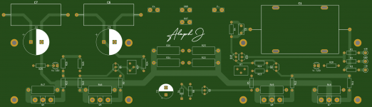
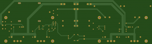
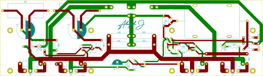
I decided for myself that I want to build Alep J sometime in 2021-2022.
looking at Aleph J DIYAudio boards and parts I thought I want C1, C6, C7 to be big fancy axial foil capacitors. (Why not? This is DIY)
But fit them to DIYAudio boards would be kind of hard.
Looking at DIYAudio Aleph J scheme I was thinking maybe I could build boards for my needs myself and also want it to be UMS (Universal Mounting Specification) friendly.
Reading a bit in Software Tools threads and found my software to try and learn would be KiCad.
It's not newbie friendly and took 1-3 days of youtube learning lessons to start doing something.
So it started as hard and I stuck on every two steps then It become easy and.. hard again but fun.
Drawing layout is a maze puzzle. Just when I thout I have nice layout on some parts I stuck in a dead end trap on other parts so I move them countinously and redraw layout lines.. 😀
So.. I drawing Aleph J boards for left and right chanels (only left chanel right now) compatible with UMS heatsinks and with some specific axial capacitors.
I am not EE just hobbyist with basic knowledge so there could be errors and I also need a cricical view.
Thats what I have right now.
It took me 2 weaks drom installing KiCad to this but I am not in haste and have a lot of time to slowly make it better.
Board size is 75x260mm (2.95x10.24 inches).
P.S.: A little invention is tht pads on C1 for nylon zip ties. 😀
Big axial cap is heave and it will stress pins with his weight.
Attachments

I want C1, C6, C7 to be big fancy axial foil capacitors. (Why not? This is DIY)
The bigger the more they will act as an antenna that picks up noise. I'd recommend to stay away for physically big caps if/where possible.
- Home
- Amplifiers
- Pass Labs
- Aleph J for Universal Mounting Spec