45.1584MHz and 49.152MHz
This frequency is used for reclocking. We do a divide by 2 (resulting in 22.5792MHz and 24.576MHz)for clocking DAC chip, SRC4392 and XMOS USB receiver.
This frequency is used for reclocking. We do a divide by 2 (resulting in 22.5792MHz and 24.576MHz)for clocking DAC chip, SRC4392 and XMOS USB receiver.
Volumio says there is no i2s Dac that has direct dsd capability except USB dac, I guess that is why AK4490 only can accept 24/192 with i2s input only.
So for this AK4493, how will this flow in i2s dsd128 being decoded? I say dsd128 because the fifopi can only decode DoP128 and output as i2s source, if my understanding is correct.
So for this AK4493, how will this flow in i2s dsd128 being decoded? I say dsd128 because the fifopi can only decode DoP128 and output as i2s source, if my understanding is correct.
This is taken from the datasheet.
"The AK4493 has automatic mode switching function that determines DSD or PCM/EXDF mode from input signals of the BICK/BCK/DCLK pin (#3), LRCK/DSDR pin (#4) and WCK pin (#6). This function is available by setting ADPE bit = “1”"
It does not detect DOP. The ES9038Q2M can detect DOP but not the AK4493.
And it bothers me that the FIFOPI has no Mute signal nor DSD/PCM signal. (Maybe a suggestion to ian!??)
I mean fifopi will decode dop128 based on Max dop rpi can support to native dsd128 and then it can be output as i2s to AK4493. About dsd/pcm signal I can ask.
I think there is some confusion starting here.
I do think that the 'DAC hat' solution, if developed on purpose by Sonny - can be a great idea. So it is really very interesting what you (all) started here.
But.
I think an alternative solution to the "classical' line is interesting mainly if it might/could also offer quality advantages.. If you are just assembling something because you might think it is better..
Like the on-board Xmos DDC solution, even the 'old' classic one offered by Sonny is doing DSD native 256 without a hitch... now to change that to a DoP 128 solution from the RPi.. why?
Now. Second part - as a teaser, I would like to show here some recent advancements. I am still tweaking the old V 1.0 version, upgrading the clocking system, the clocks, the power supply distribution etc.
Lately I have discovered a little further tweak which I feel further cleaned up the already very good results obtainable from this little Dac. (V1.0, modded)
For comparison, I would show here the 'classic' results that I regularly obtained from the 'previous level upgrades'.
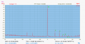
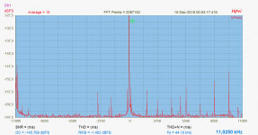
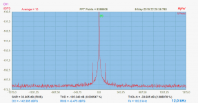
First is the distortion spectra, second graph is the jitter spectrum from the end of 2018:
I do think that the 'DAC hat' solution, if developed on purpose by Sonny - can be a great idea. So it is really very interesting what you (all) started here.
But.
I think an alternative solution to the "classical' line is interesting mainly if it might/could also offer quality advantages.. If you are just assembling something because you might think it is better..
Like the on-board Xmos DDC solution, even the 'old' classic one offered by Sonny is doing DSD native 256 without a hitch... now to change that to a DoP 128 solution from the RPi.. why?
Now. Second part - as a teaser, I would like to show here some recent advancements. I am still tweaking the old V 1.0 version, upgrading the clocking system, the clocks, the power supply distribution etc.
Lately I have discovered a little further tweak which I feel further cleaned up the already very good results obtainable from this little Dac. (V1.0, modded)
For comparison, I would show here the 'classic' results that I regularly obtained from the 'previous level upgrades'.
First is the distortion spectra, second graph is the jitter spectrum from the end of 2018:
Attachments
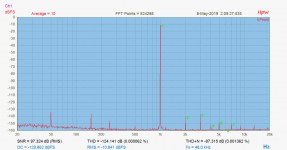
After this last little correction in the power supply topology,and some new power supply modules applied the same measurements look like this:
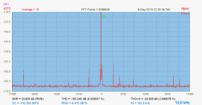
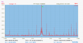
first is the distortion plot taken same days ago, second is the jitter spectrum, third is a zoom-in in the jitter spectra.
Again: this is obtained with the 'old' Xmos implementation, (no galvanic isolation scheme), NDK SDA clocks on board, new LT3045, LT3094 preregulators, slightly modified discrete output shield with updated SITO discrete opamps, differential output into the RTX6001 diff. input.
For the jitter measurement the Mirand V1.0 had been driven 384kHz/24bit resolution, 12kHz test signal, Full scale (0dB). The recording was done with the RTX6001 ADC at 192kHz ,20dB attenuation setting, so the recorded level is -6dB.
384kHz drive was applied so as to stress the dac as much as possible. (at lower speeds the result is cleaner)
Attachments
Last edited:
There's too many DAC hats out there already, so much choice... I'm in for classical DACs as well. Limitation on the i2s is an important factor for higher resolution files, especially if you're into DSD format.
Nice work Joseph!
Do
Nice work Joseph!
Do
Finally here is a loopback test of the RTX6001 analyzer itself, it's built in dac / ADC driven at 192kHz (the max. possible). So the jitter spectra is in a slight 'advantage' with respect to the 384kHz testing.
As visible, the artefacts around -9600 Hz and the modulation lines around the carrier at ~+-1400Hz are common to both the previous and this graph, so most probably a product of the RTX6001 ADC itself.
As visible, the artefacts around -9600 Hz and the modulation lines around the carrier at ~+-1400Hz are common to both the previous and this graph, so most probably a product of the RTX6001 ADC itself.
Attachments
Limitation in the I2S mode:
Let's clear it up thoroughly:
In the V1.2 design a texas SRC4392 sample rate converter took care of all input formats, except for the on-board XMOS USB / I2S conversion.
So external I2S, SPDIF, AES signals were received/ managed by the 4392.
This had imposed a limit in the I2S capabilities.
If Sonny produces a 'pure dac hat' version, it will not have any on-board converters, I suppose..
In that case the inherent capabilities of the 4493 chip itself are the determining factors.
Up to DSD512 / PCM 768.
Ciao, George
Thank you very much to take time to explain the advantage of usb implementation. I tried to read it few times to understand it. I am sorry and it is not my intention to cast doubt on the usb input on Mirand dac. I didn't know that i2s dac has limitation on playing dsd files. And all my dacs are usb dacs, I never own one i2s dac before. So I just wonder what is the possibility if bypass the usb input.
So far to my ear, I have listened to few dacs which I think the spdif input is sounding better than usb input. Therefore I made the request to have i2s input that can bypass usb and play up to max dsd rate possible.
If this request can cause disruption to the perfectly working dac, just forget about the request. I can happily stick to 3.3v cmos level i2s to play at 24/192 rate.
Just to let you All know... I got home to this. Of course there is a little work to be done tomorrow.... But at least there is progress. So right know i have 3 dac boards 5 preamp, 6 discrete output boards, 4 xlr front end for Mirand A1. V1. 2 and 5 oled panels, 6 encoder.
It is not enough and I will push on, regarding assembly...
It is not enough and I will push on, regarding assembly...
Hi Sonny,
If I want to get the new preamplifier, will it work with my current DAC 1.0 and Oled display without modification, or I need a new firmware?
Thanks
Do
If I want to get the new preamplifier, will it work with my current DAC 1.0 and Oled display without modification, or I need a new firmware?
Thanks
Do
Regarding the DAC board classic...
It is getting upgraded... I am adding the atmega328pb to it as well.
If you should make a difference as a hat for the rpi. Then We have to get rid of the i2s build into the broadcom and make a i2s/dsd implementation in an fpga with fifo buffer and high / low water mark.
The Micro processor is fast but interrupts have high latency compare to a Micro Controller....
With external i2s/dsd implementation it would really move forward... But that would require the interface in linux to get a New patch.
Then it would be a short er path than over USB and clean er.
It will work.... We just need to Check firmware because the attenuator is made with dac8812... So check if it is dac8812 or Dac8802 on your old preamp.Hi Sonny,
If I want to get the new preamplifier, will it work with my current DAC 1.0 and Oled display without modification, or I need a new firmware?
Thanks
Do
The USB input should still remain even I request extra feature to bypass it. Because in the end i dont know which one i will end up with and I also like this USB feature very much which I don't see in other dac:
So don't throw the baby out with bath water.
USB is galvanic isolated now. We use a DC/DC converter from Murata, but it can be feed with an external +5V source that is isolated. J11 is the input for that voltage. J13 is a control signal for an external source if you want’s to turn it off
So don't throw the baby out with bath water.
The USB input should still remain even I request extra feature to bypass it. Because in the end i dont know which one i will end up with and I also like this USB feature very much which I don't see in other dac:
So don't throw the baby out with bath water.
?? I did not get that.. [emoji2955],,
I just need to be sure. Before i hit 'enter' and starts drawing a pcb.... It is 2 days work....
I mean the new board AK4493 should have have all input features of AK4490 which is SRC4392 for spdif and xmos usb input that applies full galvanic isolation and also can be fed with external power. Besides it also have u.fl connections for direct i2s input which bypass usb xmos input if need to be. That is what I meant.
- Home
- Vendor's Bazaar
- AK4490 USB Dac with dsd support.