Keep posting, please!
Mark,
Diffraction: good point, I expected to have to recess the WG and 3FE25s, but didn't see a problem on the test baffle, and was lasy when I made the speakers.
Ring of five 3FE25s: how distant are you measuring when you see the peaks separated by .11ms or ~3.7cm? (on axis, I assume). Too close? Or are you seeing diffraction at frequencies that won't be present with the crossovers in place?
The ring's radiation pattern can be (should be) "whacky" but - following the Horbach-Keele idea, or BButterfield's variant - the blend of inner ring and tweeter can be fine. I'm not sure how this will work out with your tweeter - that's what I meant by problems around 3kHz a few posts ago. You might have to let the directivity fall from 2-4 kHz.
It's perhaps easier to play with blending the 10s and 3s first. You make FIR filters, correct? If so, you can go straight to using BButterfield's formulae for 2nd order sections. The 3FEs are so flat that you don't need to equalize them first. Looking at the 10FE datasheet, it could be better to use FIR to equalise them flat first, based on a close-mic (up to >1 kHz). Avoiding that is a reason I like the smaller drives in the outer ring.
The pattern from each ring should of course collapse down to a narrow lobe but with decaying gain up through the crossover region. There will be side-lobes, but if you get the crossover right they can be kept do to around -10dB out to quite large angles. They get bigger until the crossover is applied, of course. The next band up fills in the holes between the lobes, so the lobes from the lower band are well hidden in the summation.
Then use the same low-pass filter scaled to say 2.5x higher frequencies for the inner ring and see if you can find a HP for the tweeter to match.
There's quite a lot to juggle, and the first array in this thread took days and days of measurement and crossover experimentation.
Ken
Continued thx Ken,
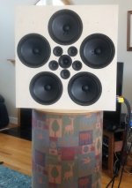
I figure since i have to go to the trouble of getting a flush-recess mount for the tweeter, i might as well do the same for the 3fe25's (which are a PIA with their mounting tabs), and the 10"'s.
Gonna put a 9mm sheet of BB over existing baffle, and shim/route the various drives to flush fits.
And i think i need to do this flush mount for the 3fe25's to determine why the dual impulse peaks exist.
I measure the dual eaks at any distance from 1 to 3m, onax to +/- 20 deg.
Since they are so closely spaced at 0.11ms apart (approx 9 kHz WL), I can't rule out diffraction...especially since i barely know what it is lol.
If I didn't measure them on axis, I would probably just chalk them up to geometry to mic, ie different off axis time arrivals.
When I say the 3" rings radiation patterns go whacky, I mean solely within the range i hope to use them..which right now would be from about 400Hz to 1.5-2kHz.
This is either raw, xovers-only in place, or full flattening with xovers.
I even questioned if I had any polarity mismatches.
It's why i'm praying for some diffraction effects !
Yes, I use FIR (and linear phase xovers).
The one part of this project i feel 100% confident to handle, is the xovers, and finding/blending radiation patterns.
(If more folks only knew how much easier lin phase is to work with...😉)
Hope to get baffle fixed tomorrow...
Pause for thought
Mark,
I've been looking at your design to see if there are any useful comments I can make. I'd not appreciated how quickly you would cut wood - I'd still be musing or making test baffles 6 months from now.
Measuring from the photo above, I estimate ~10" radius for outer ring and ~3.5" radius for the inner. A ratio of 2.9:1, which is on the large side; that will make it harder to integrate the rings. Integration is easiest with a 2:1 ratio and wide coverage and gets harder as the ratio increases or the coverage narrows. Note that I chose a ratio <2:1 in the latest array.
Let's say the outer ring is directional above ~500Hz - depends on the angle for which you choose to design. The inner ring would then have matching directivity at ~2.9x500Hz = 1.4-1.5 kHz.
The problem I have with this choice is I don't see how to blend the rings very well in the range from 1kHz to 1.4 kHz: seems to me that you'll need to let the pattern narrow and broaden again (that's guesswork, not a model).
What about tweeter integration? For you this is much the same as the problem of integrating an 8" mid with the chosen tweeter: in the horizontal plane - that's a benefit from symmetry, only one problem to solve. I write 8" as most 8" mids have 7" cones.
Aside: if you are concerned about multiple impulses from the 3FE25s, think of those as coming from parts of an 8" cone - but with holes, so the sound doesn't arrive from the whole surface.
If you "pretend" you are making a standard 8" two-way with your tweeter, you should end up with a reasonable starting point filter. It's the standard dome-tweeter problem only marginally helped by the waveguide: it's hitting the directionality (I guess) you want above ~5kHz while the inner ring is reaching to 2.5kHz at best.
Given the above, I'd likely choose to run the outer ring to 800Hz and the inner to
2.3 kHz where it is 10dB down at ~45 degrees. With the tweeter something like 10dB down at 1.2 kHz (as well as another 3dB chopped off the tweeter response to flatten it below 5kHz).
How would that sound? Of course that depends on the room. It's worth throwing together some FIR filters and trying that. It might be better than you expect.
At the moment, I'm not sure what else to suggest.
Ken
Hi Ken, really good stuff 🙂
Your explanation or radius ratios makes total sense.
I had built a speadsheet for pattern control, based on ka charts, and also on Dunlavy's formula for coverage angle, = 57/(diameter/wave length in inches).
But i hadn't yet connected the diameter ratio rule of thumb, you showed me.
Your radius estimates were dang good !
3" is 3.625", 10" is 9.75". I don't really know how to spec the tweeter, but the curvature in the waveguide ends at about 1.44" radius.
Big question...when you say radius....
do you mean to driver centers (seems so) or to outer periphery ?
Which do you find correlates best with off angle measurements?
Ideally, I'd like about a 80 degree pattern control.
I get the contraction-vs-widen blending game between driver sections.
Re-looking at measurements, I'm guessing 600Hz and 1600Hz might be best xover point compromises with the drivers in play.
Oh, and pls don't ever think I'm invested in a design I'm working on...
I'm a build, measure, rebuild, re-measure, on and a on type guy....simply cause it's easy and fairly cheap for me, and i feel i learn alot doing so...
So tell me straight. and trash me ideas away 🙂
Good questions
The standard formula for coverage is the place to start.
Here's how to understand the radius: the small drives that make up the ring act as point sources, and to a first approximation those drives can be replaced by points on the ring. I've checked this by simulation, for the rings in my speakers, and it's a close match up into the crossover range for each ring. I did a quick (i.e.<30s) simulation of a ring of five 10"s in Edge and it's the same with a ring like you have: changing the drive size from 10" to 1" barely changes the response at 30 degrees up to ~900Hz. A nice thing about Edge is that you can adjust the size of all elements with a couple of keystrokes. Above 900Hz, 10FE200s aren't like pistons anyway.
For 80 degrees, I would look for a much more directional tweeter: down to well below ~1.4 kHz. - probably a CD+WG. Unfortunately there does not seem to be anything commerically available. [For my own use, the best I could think of was taking a mold from one of my Harpers and modifying that to include space at the edge for a ring of mids - that's a little wider than your 80 degree target].
I believe 1.44" is an over-estimate of the effective acoustic size of the WB WG (look at the coverage at 5kHz shown on the datasheet). Anyway, what matters is the pattern in the overlap range with the inner ring - you need to find a way to merge them together keeping the summed pattern as smooth as possible.
My AMTPRO design managed to yield narrow vertical coverage by using six drives per band, including drives close to the tweeter. This knocks the worst lobes down, but can't be done in two dimensions at once.
You might think of something like an XT1086, but the narrower vertical radiation and pattern flip breaks symmetry, and forces the rings to be distorted too. I'd recommend a (non-existent?) circle, square, or -for you - a regular pentagon.
As an example, if the XT1086 has acceptable coverage above 1.4 kHz, you'd want to transition from inner ring to WG from 700 to 1400Hz (and suitable CD). With the 10" wide WG a ring of 3FE35s is a little too wide for an easy transition. There might be a compromise to be had there, however, as the gap is not huge (I did a quick sim in edge with 6 3FE25s close packed around the outline of an XT1086).
I gave away my XT1086s years ago - I didn't like the sound at ~5kHz.
A better approach would be to use "mabat"s tool to design a custom 80 degree WG about that size - OS with a roll-over suited to the purpose.
I'd probably start around 22" for an outer ring (perhaps of four 10s). (Other than Edge simulations, picturing this in my head, so unsure how it all fits together.)
If there was something like an XT120 but circular (say 7" OD) I'd have tried that with a ~10" ring. Follow that logic a few more compromises, and you see the path I ended up taking.
Ken
Last edited:
Mark
Quoting myself: "I believe 1.44" is an over-estimate of the effective acoustic size of the WB WG" is not well phrased.
The WGs on your tweeter and mine are not approximated by a piston radiator of any size. That's the point of constant directivity waveguides. The rest of the paragraph stands.
The rings can be modeled as pistons as a starting point, but the tweeter WG can't - it is not right to think of an equivalent diameter when there's a WG.
The W148+tweeter combi that I use is about 6dB down at +/-60 degrees off axis at 1.8-2kHz, narrowing slowly to ~90 degrees full-width at 10 kHz. At ~1kHz it's close to a point source with roughly the same sensitivity as the naked tweeter has at 3kHz.
Even with this friendly tweeter+WG, integration with the inner ring is not easy. There are very few combinations that do as well as this.
If we believe the datasheet, the SB26STWGC waveguide is directional above about 3kHz suggesting an inner ring considerably less than half the radius of the one I use. That is impossible with the 3FE25. Even a ring of 1" Aurasound units or similar right against the tweeter would be a little too large.
The SB tweeter might be more directional than the datasheet suggests, even so, there's a gap to fill.
Ken
Last edited:
Hi Ken, everything you are saying makes good sense to me.
And i can easily see that the selection of the VHF component, getting the needed SPL and required low frequency extension, while keeping size down .....is the component around which all else is built....particularly the critical inner ring.
Your W148+ tweeter looks really good. Congrats on all the work it no doubt took to fit the AMTPRO to the guide.
Yeah, i wish the XT120 was round too. ...(with a 150mm dia)...
I've been trying to find the pattern specs/polars for the Ciare CT440..it looks interesting.
I hear what you're saying re the SG26 directivity...
I know i need to, but i haven't stopped to look at Edge, or any type simulation for these...
Because mainly as mentioned before, my forte is cranking out inexpensive prototypes till i think i understand things. Then make final driver purchases and spec out the ending build.
Maybe not the most efficient way to do things nowadays, but honestly, i enjoy the build and measure process.
And i often get surprised by measurements ....like how much flush mounting the drivers in current project has helped smooth response of the SG26 and 3fe25's.
All i did was add a 6mm piece of BB over the existing baffle with cutouts for all the drivers ..looks better too, I think 😀
Anyway, this morning has been my first chance to try to tune with the flush baffle, and it's unfortunately an attempt made at only 1m indoors.
Because there is so much dang boat traffic out on the lake stopping outdoor measurements. (but it's really nice to see everyone having fun!!)
As near ridiculous as i imagined 1m tuning would be for this, i think results held up surprisingly well.
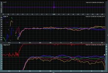
X-overs used were: for the 10"s .....100Hz LR8 & 520Hz LR8.
for the 3"s........520Hz & 1.6kHz LR8
for the tweeter.......1.6kHz LR8 & 20kHz BW4 .
(Linear phase xovers and min phase EQ's based off raw polar averages.)
Below are horiz polars in 10 degree increments, 0-40 deg.
1/6th smoothing mag and phase.
They go in order of the rainbow colors, ie violet =0, orange =40.
Now I guess I'm going to study your posts some more, and take a break till i can measure outside.
And i can easily see that the selection of the VHF component, getting the needed SPL and required low frequency extension, while keeping size down .....is the component around which all else is built....particularly the critical inner ring.
Your W148+ tweeter looks really good. Congrats on all the work it no doubt took to fit the AMTPRO to the guide.
Yeah, i wish the XT120 was round too. ...(with a 150mm dia)...
I've been trying to find the pattern specs/polars for the Ciare CT440..it looks interesting.
I hear what you're saying re the SG26 directivity...
I know i need to, but i haven't stopped to look at Edge, or any type simulation for these...
Because mainly as mentioned before, my forte is cranking out inexpensive prototypes till i think i understand things. Then make final driver purchases and spec out the ending build.
Maybe not the most efficient way to do things nowadays, but honestly, i enjoy the build and measure process.
And i often get surprised by measurements ....like how much flush mounting the drivers in current project has helped smooth response of the SG26 and 3fe25's.
All i did was add a 6mm piece of BB over the existing baffle with cutouts for all the drivers ..looks better too, I think 😀
Anyway, this morning has been my first chance to try to tune with the flush baffle, and it's unfortunately an attempt made at only 1m indoors.
Because there is so much dang boat traffic out on the lake stopping outdoor measurements. (but it's really nice to see everyone having fun!!)
As near ridiculous as i imagined 1m tuning would be for this, i think results held up surprisingly well.
X-overs used were: for the 10"s .....100Hz LR8 & 520Hz LR8.
for the 3"s........520Hz & 1.6kHz LR8
for the tweeter.......1.6kHz LR8 & 20kHz BW4 .
(Linear phase xovers and min phase EQ's based off raw polar averages.)
Below are horiz polars in 10 degree increments, 0-40 deg.
1/6th smoothing mag and phase.
They go in order of the rainbow colors, ie violet =0, orange =40.
Now I guess I'm going to study your posts some more, and take a break till i can measure outside.
Attachments
Mark,
looks promising.
The directivity broadens at the two X-Os. You've got too much of the inner ring at 520 and too much of the tweeter at 2k. The latter is as expected, probably hard to solve, the lower one should be fixable using a different crossover (higher, shallower).
Ken
looks promising.
The directivity broadens at the two X-Os. You've got too much of the inner ring at 520 and too much of the tweeter at 2k. The latter is as expected, probably hard to solve, the lower one should be fixable using a different crossover (higher, shallower).
Ken
Yep thx, i think that about the rings' xover points too.
I was actually trying to optimize at 1m, vs the raw polars, just for ring-tuning practice, knowing it's more hokey than not.
I saw that response for both the 10" ring and 3" ring fell super fast up so close, as angle and freq increased.
So I let the xover points move low enough to handle the response fall off.
I'm completely sure xovers can move up when at a more reasonable distance.
Plus, need to get the SG26 above 2k just for SPL safety room, i think.
Oh, i did try shallower xovers....was worse all around...
Tried steeper too, no real improvement....
Last edited:
Ken,
You are clearly correct about the difficult matchups I threw together.
Outdoors, testing at >3m did not solve the rather drastic narrowing up close indoors that was forcing lower xover points of both the 3" ring or the 10" ring when off-axis more than 20 degrees.
The 3" ring is pretty much unusable above 1.7kHz. The 10" unusable above about 650Hz.
And I've seen the SB26 has some very nice curves when on its own smooth baffle, but the flush plate overlay has overcome only about 1/2 the diffraction issues.
So, it's scrap-pile time for round one!!
Time to rethink, study some more. (which btw, sorry for getting your projects confused as to where you currently are...)
Anyway, these arrays are really intriguing...thx for the nice help...
Mark,
if you decide to come back to this idea, want to stay with the large outer ring and still aim for ~80 degree coverage, I think you'll need to find a much more controlled tweeter or add a third ring.
The main reason I've not tried a third ring is that I'm out of DAC/DSP and amp channels. In such an approach you would expand the 3" ring somewhat and squeeze either the larger tweeter WG or a third ring into the space.
Some idle musing follows:
I'm keeping an eye on mabat's "Ath" thread, to see if a useful design pops up there - though that would leave the problem of modifying the shape to accommodate the inner ring and getting it made - unlikely to be a low-budget option.
The idea of fitting an inner ring behind the baffle around the tweeter, with ports to transmit the sound in ring close to the tweeter, had come to mind - i.e. close to MEH as possible without having the mids inside the WG. This has advantages and disadvantages.
In the end, I discarded this idea as the Helmholtz resonant low-pass filters formed by the ports have to be exceedingly precisely made to avoid variation of response among the mids (if they are to yield well-matched responses at say 3kHz). This approach probably needs CNC or high quality 3D printing to have a chance of working - holes drilled in MDF were no where near good enough. In retrospect that's the same problem I had with MEHs - I couldn't make the wood nearly precisely enough to get the results I wanted.
Ken
I'm keeping an eye on mabat's "Ath" thread, to see if a useful design pops up there - though that would leave the problem of modifying the shape to accommodate the inner ring and getting it made - unlikely to be a low-budget option.
I have been looking at Follgott's Quasi Coax and bbutterfield's Fractal Array again recently as a future project. I have some ability in using "Ath" to get what I want so I might be able to help design something. What do you think would would be ideal for this purpose?
Fluid,
good question.
I started out aiming for narrow vertical response, where it's easy to get a smooth horizontal response by putting mids close to the vertical axis of symmetry. It's a good solution, given a tweeter with the correct horizontal and vertical directivity.
With dome tweeter a waveguide is needed, and if its height and width aren't equal there will be pattern flip, which then tends become part of the response down to all lower frequencies, which doesn't make sense to me (the alternative is to flip back, but then what's the point?).
That leaves the challenge of integrating the tweeter+WG with the innermost ring of mids. In an MEH, if the WG is big enough to fully exploit the frequenct range of the mids - the same problem occurs on the next ring out, nothing has been solved, and we'll end up with a full MEH solution (see elsewhere). That fails for me as I want speakers that are shallow against the wall.
As Mark and I both found, it's hard to source a WG and mids that will fit closely together to give good integration, at least if conventionally baffle-mounted. The smaller Aurasound etc. units might provide options (but I wanted to keep the sensitivity roughly equal over the frequency range).
The problem is to find a better way of integrating a WG and mids: either extending the WG down to lower frequency (a lot lower in Mark's case, less so in my case) where the gaps between parts become less significant or forming a custom waveguide with the mids integrated into the surround - needs CNC/3D printing. That comes closest to the "flattened MEH" solution, especially if ports are used on the mids (but see my comment about required precision, it's not like in a true MEH where small differences among the mids can average out inside the WG). It's probably the case that anyone who can make one of mabat's designs with precision can integrate ports and mounts for mids into the periphery.
Even though the chances of me going down that route in less than a decade are slim, I've been watching for hints.
The general idea is that the mid ports would be on the roundover, not in the main-WG (so with much less coupling to the WG to blunt the reflection null) and where they don't scatter nearly so much of the higher frequencies (as they do in a true MEH). Sketch designs & calculations of the Helmholtz low pass filtering, suggest that the ports need to be wide and shallow to get enough bandwidth - there are many parameters to juggle.
Hopefully that conveys the idea, I'll leave it there for now.
Ken
Last edited:
Coaxial driver in the middle, or MEH 🙂 It is almost impossible to get drivers close enough if waveguides are involved.
This is about the point where I couldn't decide which way I wanted to go either 🙂Fluid,
good question.
I started out aiming for narrow vertical response, where it's easy to get a smooth horizontal response by putting mids close to the vertical axis of symmetry. It's a good solution, given a tweeter with the correct horizontal and vertical directivity.
With dome tweeter a waveguide is needed, and if its height and width aren't equal there will be pattern flip, which then tends become part of the response down to all lower frequencies, which doesn't make sense to me (the alternative is to flip back, but then what's the point?).
I've built a full range line array for vertical directivity control. It works really well and is the best speaker I have owned to date but it is not plug and play in any way.
The line array overcomes the narrow vertical sweet spot of a ribbon in that the response moves vertically as you do.
I have got some Aura NSW2 drivers and a Celestion 1" CD that I bought to use in a Synergy style speaker that has never progressed out of the thinking stage due to the complicated construction.
I have now bought a CNC router kit to build and I am hopeful that will give me some flexibilty in building these sort of things once I get it going so I am considering these projects more seriously now.
Perhaps a MEH horn stub at the centre with the Aura's built into an Ath Guide and a ring or fractal arrangement of woofers might be worth a try.
Hi Ken, fluid, tmuikku,
Great discussion. Imho, these spacing / pattern control issues are at the heart of speaker design....and nothing better than a flattened Synergy or MEH to illustrate it.
Ken, i'm going to keep looking for the smallest super-tweeter, bullet tweeter, etc that might mate with a ring of Auras or similar such around it, crossing at maybe 3-5kHz ( anybody tried one of the Motorola piezos on a small wave guide? )
This appears in line with one side of your musings I think; the other side being the use of a larger tweeter with a wave guide.
In either case, it seems the outer diameter needs to kept under around 8", for cross to next ring at about 1.5k.
But all this is mere continued mulling so far....
Part of me just wants to mount a trusty xti-1464 & CD on a baffle, and surround it with rings of TC9's pulled from some line arrays sitting in storage. Hmmm, may damn well do this with the previously mentioned XT-120.....
Then play with dsp frequency shading strategies, like previously done for the straight line array, but now based on radius. (I think I'm ok with enough dsp/amp channels.)
Having written that, I guess a really cheap way to experiment would be to just mount a bunch of TC9s in rings around a central one. And use the only the center one for VHF, knowing there won't be enough output for a real speaker, but enough to learn from...
Anyway, whichever way i go, i don't think it will be to try to make a full SPL, 100Hz up, speaker again.
For me, it seems the best first step with these ring arrays is to find a tweeter & first-ring integration; small enough, low enough in freq, and loud enough, to allow a second ring to take over maybe in the 1-1.5kHz camp.
10"s are headed back to storage for a while.
Quick replies
Mark
I looked at the XT1464, but a) too narrow, b) quite deep and c) pattern flip. Perhaps it can still work well. It's one of the better options with regard to pattern flip, and others may not mind the depth.
tmikku
Coax is a decent option which I rejected: they tend to be deep and optimized for entirely different applications - perhaps there's a 6 or 8" one that would work, but I'd only be using it above ~2 or ~1.5 kHz. Like the MEH there's no benefit (in this application) to extending the bandwidth down without providing directional control.
Fluid
It would be great to see that!
and
100% agree.
Ken
Mark
I looked at the XT1464, but a) too narrow, b) quite deep and c) pattern flip. Perhaps it can still work well. It's one of the better options with regard to pattern flip, and others may not mind the depth.
tmikku
Coax is a decent option which I rejected: they tend to be deep and optimized for entirely different applications - perhaps there's a 6 or 8" one that would work, but I'd only be using it above ~2 or ~1.5 kHz. Like the MEH there's no benefit (in this application) to extending the bandwidth down without providing directional control.
Fluid
Perhaps a MEH horn stub at the centre with the Aura's built into an Ath Guide and a ring or fractal arrangement of woofers might be worth a try.
It would be great to see that!
and
For me, it seems the best first step with these ring arrays is to find a tweeter & first-ring integration; small enough, low enough in freq, and loud enough, to allow a second ring to take over maybe in the 1-1.5kHz camp.
100% agree.
Ken
Originally Posted by mark100:
For me, it seems the best first step with these ring arrays is to find a tweeter & first-ring integration; small enough, low enough in freq, and loud enough, to allow a second ring to take over maybe in the 1-1.5kHz camp.
Yes, I have been pondering these ideas, drawing some simple CAD models to see how close I could get the first ring (considering machining driver frames, etc.). This thread prompted me to re-visit.
My current idea is a Bliesma T34 tweeter, trying to get the XO down to ~ 1.3khz. First-ring candidates include the SS10f, SB65, and the Wavecor 4" woofer (available with truncations). This would be an expensive experiment, obviously. Lower crossover hopefully down into the room's modal range (at least 300Hz, ? 100-200).
While those mids are close to pistonic up to the XO (the tweeter will be radiating at 180 degrees at that point), the first ring (though the individual drivers will be 180 degrees), will not when looking at the ka for a composite driver with the diameter of the ring.
I also looked at the Wavecor TW030WA13 (with WG), but while allowing the goal crossover, the small WG doesn't allow pattern control down to the desired XO. So bigger WG needed, but then bigger first ring....all like you described above.
I have considered MEHs, but am not terribly enthusiastic (though maybe with an ATH design as suggested).
If we want vertical pattern control an array of ribbons (the only way to control C-C distances) adjacent to a line of the above mids would allow this with matching dispersion horizontally (though 180 at XO).
Lots of parameters to juggle, sort of like trying to hold 10 ping pong balls under water...
Bill
Mark100 prefers building to simulation; I'm the other way around - simulate many times, build only once (or twice 🙂).
Not too long ago I simulated something close to what you are doing - tekton tweeter arrays in this thread
https://www.diyaudio.com/forums/multi-way/336743-help-understanding-tekton-tweeter-array-schematic-6.html#post6316442
near post 54...
My best response was with an array of DMA45 1.5" full range driverrs. When I replaced the central driver with an OC25 tweeter, the polars weren't quite as good. One needs a minimal waveguide to control the tweeter and then you get the spacing issues you've been discussing. Using 1.5" drivers for the mids helps...
The beauty of Vituix is if you have the directivity of individual drivers, then it can calculate the polars of the array. For cone drivers, its baffle diffraction tool does a decent job of synthesizing drivers for a quick look. For a waveguide, you would have to measure.
So if someone posts directivity files for a small waveguide, it would be fairly easy for me to put a Vituix sim together like I did in the referenced post.
- Home
- Loudspeakers
- Multi-Way
- After a decade of planning, thanks to forum members